This post is older than 2 years and might not be relevant anymore
More Info: Consider searching for newer posts

Thingy91 UART External communication

Hi Dev Team,

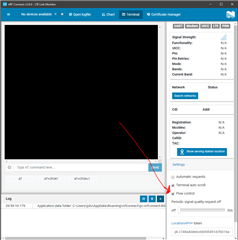
I was working on the Nordic Thingy91 and had to establish an external communication of a sensor to the Thingy91 through a UART. 

For this, I was looking into the GPIO's to check which pins can be used for my Tx, Rx, CTS, RTS. 

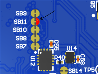
I found this link : https://devzone.nordicsemi.com/f/nordic-q-a/64742/nordic-thingy-91-pin-name/264224#264224 that talked about using anything between P0.18-P0.25 (MCU_IF0-7).

https://github.com/nrfconnect/sdk-nrf/blob/master/boards/arm/thingy91_nrf9160/thingy91_nrf9160_common.dts#L165-L182

These are said to be connected to the nrf52840 interface. Can I just use these pins for my external UART connection ?

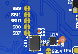
Also, I wanted to know the functions of these Test pads (TP). Can the test pads be also used for UART communication?

If so, how will it be defined in the thingy91_nrf9160_common.dts file. 

Regards,

Adeel.

Parents Reply Children
  • Hi Jonathan,

    I tried using my Thingy91 for external uart communication. 

    It all went pretty well except for the receiver pin. Now, I wanted to use any of the pins from MCU_IF[4-7] to test the receiver input..

    For that, I was looking to use MCU_IF[7] : P0.25 by cutting the SB11 and I have configured my UART 1 as follows now : 

    &uart1 {
    	current-speed = <9600>; 
    	status = "okay";
    	tx-pin = <13>;
    	rx-pin = <25>;
    	rts-pin = <14>;
    };

    I just wanted to know if cutting the SB11 would have any have effect on my logging on the LTE Link monitor ?

    Regards,

    Adeel.

  • Hi Adeel,

    Cutting SB 11 should be fine, and it is always possible to revert the effect by soldering the two half's of the SB pad together. 


    Regards,
    Jonathan

  • Hi Jonathan,

    Thanks for the answer, will do that. I will cut the solder bridge and try it.

    I can connect the Rx wire to any one side of the SB11 pads rite ?

    Regards,

    Adeel.

  • After cutting SB11 one side is connected to the nrf9160 and the other is to the nrf52.


    The right half of the pad is connected to nrf9160(Red highlight). Since you want to use talk to the nrf9160 you should connect the RX wire to the right side of the pad. 


    Regards,
    Jonathan

  • Hi Jonathan,

    Thanks a lot, I did that and tested it. I actually did it to test another receiver pin. 

    I was trying to get an answer from my sensor on my Rx. I see the data on my receive pin and that data is correct. But when I try to read the data on my Link monitor, I get different hex values. 

    For example, I see (01 04 04 43 92 08 F6 C8 6B) on my receiver pin through my oscilloscope which is the correct data I need. But when I view the same on the link monitor, I see different values (79 FD F7 F7 EF 29 E0 E0 E0) and I see these values as well in my uart_buf when I debug the code. Its a very strange behavior I am noticing on my Thingy91 as I don't receive the correct bits when I view it, but the correct data is present on the pin when I measure through the oscilloscope. 

    For testing reasons, I changed my receiver pin now to P0.25 (previously it was P0.16) but the behavior is pretty much the same. 

    I had tested the same thing with the nRF9160DK before and it worked perfectly on the DK. 

    I wanted to know what could be the reason with the thingy91 and how can I debug it further ?

    Regards,

    Adeel.

Related