This post is older than 2 years and might not be relevant anymore
More Info: Consider searching for newer posts

How to modulate the voltage of a gpio for a louder buzzer

Good day,

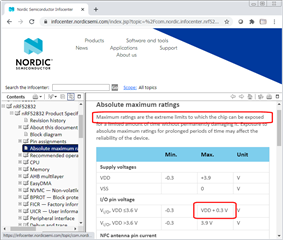
I am using a DK board with the nRF52832 (pca10040) and I am using a 4 kHz buzzer connected to the gpio 16. I have seen the examples pwm_driver and pwm_library of the SDK as well as several posts on this website. However, I only manage to get a 1.9v output and the buzzer can barely be heard. I have read in the datasheet of the nRF52832 that it is possible to obtain an output from the pins up to VDD +-0.3v, for my case I am using a CR2032 battery, but I am only getting 1.9v. I have modified the duty cycle but it has been useless.

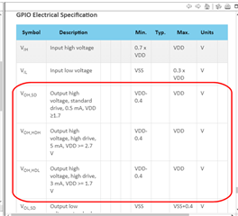
I also tried to change NRF_GPIO_PIN_S0S1 for NRF_GPIO_PIN_H0H1 in nrf_gpio.h but it was also useless, the volume remains the same.

I will leave here the code I am using in order to know if you can help me and tell me why I am not getting the 3v or tell me some other function or some other way to be able to increase the buzzer volume.

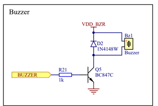
( I know that the volume can be increased using a transistor, but I would like to leave it as a last option since I do not want to add more components to my circuit, if it is not possible to increase the volume by means of software I would choose to do this.)

I really appreciate your help.

void pwm_ready_callback(uint32_t pwm_id)    // PWM callback function
{
    ready_flag = true;
}

static void sound(uint16_t freq, uint16_t time_us){
    nrf_gpio_cfg_output(BSP_LED_2);
    app_pwm_config_t pwm1_cfg = APP_PWM_DEFAULT_CONFIG_1CH(freq, BSP_LED_2);
    pwm1_cfg.pin_polarity[1] = APP_PWM_POLARITY_ACTIVE_HIGH;
    app_pwm_init(&PWM1,&pwm1_cfg,pwm_ready_callback);
    app_pwm_enable(&PWM1);
      
    ready_flag = false;
    app_pwm_channel_duty_set(&PWM1, 0, 50);
    nrf_delay_ms(time_us);
    app_pwm_disable(&PWM1);
    app_pwm_uninit(&PWM1);
 }

static void pwm_init(){
   for(int16_t i = 15; i < 40; i++){
    int16_t val = i;
    sound(val,100);
  }
    sound(800,200);
  for(int16_t i = 40; i > 15; i--){
    int16_t val = i * 6;
    sound(val,100);
  }
  sound(800,200);
}

In this case BSP_LED_2 is pin 16.

Parents Reply Children
  • Here is a good article about controlling piezoelectric buzzers.

  • Most circuits posted for buzzers are based on earlier miniature speakers, which require significant current requiring transistor drivers and - being coil devices - require stuff like reverse protection diodes to protect against back-emf when turning off the transistor drivers.

    Along came piezo buzzers, which are like capacitors, not coils,  and require very little current but instead more voltage. The best way to drive these is with a full H-bridge driver, but unlike the usual article suggestions no components are required to implement the full H-bridge driver. None; nowt; nada.

    The reason is is that there are already enough features inside the nRF52840 to create a full H-bridge driver, with sufficient current drive to satisfy the typical piezo buzzer.

    Here is the circuit; note there are no external components other than the piezo speaker:

    // Inside nRF52832/40                      Outside World
    // ====================================    =================
    //              VCC about +3 volts
    //              -------#---------#---
    //                     |         |
    //                     |         |            Piezo Buzzer
    //                   |-+         |
    //               +---|           |            +===+
    // PIN_PWM_1     |   |-+         |    Pin     |   |
    // ------------->0     #---------------O------O   O-------+
    //               |   |-+         |            |   |       |
    //               +---|           |            |   |       |
    //                   |-+         |            +===+       |
    //                     |         |                        |
    //                     |       |-+                        |
    //                     |   +---|                          |
    // PIN_PWM_2           |   |   |-+    Pin                 |
    // ----------------------->0     #-----O------------------+
    //                     |   |   |-+
    //                     |   +---|
    //                     |       |-+
    //                     |         |
    //                     |         |
    //                   =====     =====
    //                    ===       ===
    //                     =         =
    // ====================================    Outside World
    // Inside nRF52832/40                      =================

    Simply connect the piezo buzzer between any 2 nRF52840 port pins, then drive those port pins with a dual-ramp PWM. See my other posts for examples if needed, or browse the devzone. There are some posts on both music and voice.

    nrf52-midi-piano

  • Hello Dmitry, 

    Thanks for the article, I was trying with the Basic Piezo Transducer Drive Circuit, which is the same as the one Jared proposed to me in the previous answer, however I can't make the buzzer sound, unless I change the diode for a 1Kohm resistor, this way I can make it sound. However, I continue to have the same result, the sound is barely audible.

  • Hi hmolesworth,

    First of all thank you very much for the very specific answer, I will do the test using two pins as you said, it is something that had gone unnoticed. Also, I will see the other posts you have created to inform me more about this topic.

  • hmolesworth,

    I did the test with this configuration and it works much better, the buzzer sounds louder, not as I would like but it sounds a little more. 

    Thanks for the help.

    I'm still in doubt as to whether it's possible to increase the output voltage of the gpio...

Related