Good day,
I would like to start this thread by saying that I have been developing an application using the nRF52832 chip for several months, so far it has been a very difficult but not impossible journey and I have seen that I have not been the only one (https://devzone.nordicsemi.com/f/nordic-q-a/54157/difficult-to-use-nrf5x-sdk-from-scratch https://devzone.nordicsemi.com/f/nordic-q-a/21403/we-really-want-to-work-with-nordic-but-they-makes-it-hard). I started using the Keil software, but it was impossible to continue working with that software due to the problem that arises at the time of importing libraries and drivers, from the same projects that come by default in the software and the example projects that are downloaded from devzone.
So my team and I decided to start using Segger Embedded Studio and everything became much more practical and it was easier to import libraries, create new files and add them to the path, etc. (I would like to give this advice for those who are just starting with this technology and are deciding which software to use to program the nRF52 chips). Nevertheless, after several weeks, we realized that something strange happens when trying to program the nRF52832 and the nRF52810, either on the DK nRF52 board or on a custom board, and we have called it: "The Segger-Nordic effect".
Because of what happened today, I decided to share this, besides the fact that we are still trying to figure out the problem, what happens is the following:
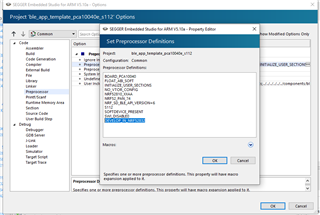
We are trying to measure the current consumption using the example ...\examples\ble_peripheralc\ble_app_template based on what is described in the Nordic infocenter (https://infocenter.nordicsemi.com/index.jsp?topic=%2Fug_nrf52832_dk%2FUG%2Fnrf52_DK%2Fhw_meas_current.html) using an oscilloscope and an ampere-meter in order to compare and verify the result.
For this purpose, we carry out the following in the nRF52 DK board:
- Cut the PCB track shorting solder bridge SB9 to put P22 in series with the load.
- Short solder bridge SB12 (if using external power supply) to bypass the protection diode which would otherwise give a voltage drop.
Since we short-circuit SB12, we add an external supply on P21 at 3.3v and add a 10 ohms resistance in SB9 and that is where we measure with the oscilloscope.
From here is where it all starts to get a little tricky:
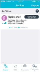
To begin, the led 1 of the board begins to blink as if it were in advertising mode and we have set an APP_ADV_DURATION of 2000, however it blinks infinitely. But when we try to search it with the Nordic nRF Connect application, the device does not appear.

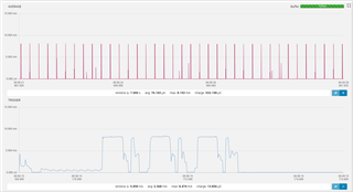
We were doing a test using the function nrf_pwr_mgmt_run(); inside static void idle_state_handle(void); in order to know how much current was being consumed when connected with BLE, We moved, changed, deleted and increased several things and we managed to see it only once and realized that it was consuming around 4 mA, but we never saw the device again.
Seeing what the function nrf_pwr_mgmt_run does:
void nrf_pwr_mgmt_run(void)
{
    PWR_MGMT_FPU_SLEEP_PREPARE();
    PWR_MGMT_SLEEP_LOCK_ACQUIRE();
    PWR_MGMT_CPU_USAGE_MONITOR_SECTION_ENTER();
    PWR_MGMT_DEBUG_PIN_SET();

    // Wait for an event.
#ifdef SOFTDEVICE_PRESENT
    if (nrf_sdh_is_enabled())
    {
        ret_code_t ret_code = sd_app_evt_wait();
        ASSERT((ret_code == NRF_SUCCESS) || (ret_code == NRF_ERROR_SOFTDEVICE_NOT_ENABLED));
        UNUSED_VARIABLE(ret_code);
    }
    else
#endif // SOFTDEVICE_PRESENT
    {
        // Wait for an event.
        __WFE();
        // Clear the internal event register.
        __SEV();
        __WFE();
    }

    PWR_MGMT_DEBUG_PIN_CLEAR();
    PWR_MGMT_CPU_USAGE_MONITOR_SECTION_EXIT();
    PWR_MGMT_SLEEP_LOCK_RELEASE();
}
We decided to directly insert the function "Wait for an event":
/**@brief Function for handling the idle state (main loop).
 *
 * @details If there is no pending log operation, then sleep until next the next event occurs.
 */
static void idle_state_handle(void)
{
       //nrf_pwr_mgmt_run();
       __WFE();
       __SEV();
       __WFE();
}
On a first attempt at making the change the device appeared, however that was just after loading the program, when changing the USB connection for external supply the device did not appear again. We did several tests until we realized that we must perform a ritual for the device to appear:
1. Ctrl + X the lines __WFE(); __SEV(); __WFE();
2. Ctrl + V the same lines in the same place.
3. Build and Run the program but with the P22 disconnected for Segger to mark the error of not finding the J-link

4. Connect the P22 pins to the 10 ohms resistance.
5. Build and Run de program.... et voilà!
We did this several times and it worked each time, until it stopped working and we couldn't see it anymore, for now we are still looking for a way to make this work. We have seen in other tests that the code sometimes does not work, but copying and pasting the same code in the same lines makes the program work. If you could help us figure out what's going on, we'd appreciate it.
We loaded the program, connected to the cell phone, measured the current and the result was: 240 uA. We only have the doubt if this is correct, since we have seen the several posts that having the softdevice must use the function nrf_pwr_mgmt_run() and not the function __WFE(); besides that is what is described in the comments of the same function. However, with this we got what we wanted, to reduce the current.
Could you give us your opinion and advice on this?
I also want to use this thread to ask:
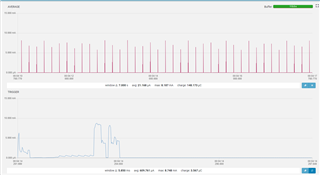
In sleep mode we have a consumption of 1 uA, in advertising mode a current consumption of 100 to 150 uA and in connected mode a consumption of 240 uA (until the last test we could see).
Is the current consumed in advertising mode normal? or should it be much lower?
Is it possible to have in connected mode a consumption of around 20 uA? The device does not perform any action, it only sends the battery level every 30 minutes using the BAS function.
I hope that this post will be useful to someone else and that you can also help me to answer the questions that have come up, thank you very much for your attention and your help.