This post is older than 2 years and might not be relevant anymore
More Info: Consider searching for newer posts

nRF52840 Overlapping .hex data & Soft Device match error

I am new to the Segger Studio and nRF52840 . (However not a Newbie to Microprocessors)

Off the Bat :- Blinky example works fine...

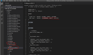
.....however when I try to get the PWM_driver example I get these errors below in picture.

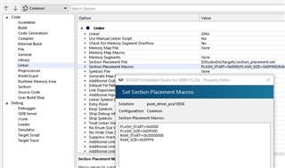
The example is for "pca10056" which is why I followed the dongle guide below, adjusting predecessor to the nRF52840 and memory macros.

 https://devzone.nordicsemi.com/nordic/short-range-guides/b/getting-started/posts/nrf52840-dongle-programming-tutorial

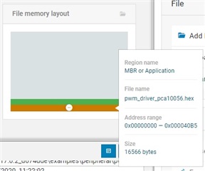
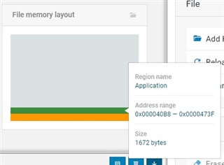
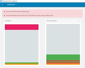
however when I port across the program .hex file and the Soft Device .hex file ( S140) there is a memory clash. I have also tried S132 (also errors).

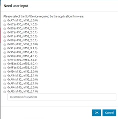
If I place just the program .hex and write to device a window pops up asking for a soft device selection !!! It does not matter which I choose (I went through all).

My Questions are :-

  1. Is there a specific soft Device for the nRF52840 ... (I could only find the recommended s140_nrf52_7.2.0_softdevice.hex ) ?
  2. How Can I tell which Soft Device is needed (i.e. from the examples). ?
  3. Can the Soft Device be Merged into code somehow in the Segger Studio ?

Any pointers would be greatly appreciated.

Parents
  • The confusing part for me is that other Project Example's (not all though) are contained with-in a folder "named" with the actual Software device required, the pwm-driver example i want to run just gives a folder marked "blank" ! no indication of SD required.

  • Yes, which means that the example doesn't include a softdevice. All of the "blank" examples are under the peripheral folder which doesn't include any softdevice. The softdevice examples are found under the ble_central, ble_peripheral or ble_central_peripheral folder. 

    The peripheral only examples are meant to showcase how to use the peripherals on the nRF without implementing the Softdevice. 

  • Memory settings as per instructions in the dongle programming "Blinky"  tutorial :-

    Step 2: Adjust the linker configuration. Set FLASH_START=0x1000 to place the application right above the MBR. You should also set FLASH_SIZE=0xDF000 to make sure that there is room for the bootloader at the end of the flash. Set RAM_START=0x20000008, as the first 8 bytes are used by the MBR for interrupt forwarding and adjust the size accordingly by setting RAM_SIZE=0x3FFF8.

    If I use the premade .hex file from the blinky "hex" folder the nRF Connect programmer  "write" is greyed-out ....so unable to send program across. (There are no  xxx10059.hex file there anyhow, i tried both the 10040 and 10056 to be sure ...nada.)

  • Please note I have change the FLASH_START=0x1000 to FLASH_START=0x0000 in the Linker - section placement-macro to try your suggestion.(the file memory layout you see above are with FLASH_START=0x0000 .. however still same problem.

  • Hi,

    See the files below and try flashing the example hex. 

    Chiprobot said:
    There are no  xxx10059.hex file there anyhow, i tried both the 10040 and 10056 to be sure ...nada.


  • As already stated in my original Question "Blinky" is working, however I am still struggling to get the PWM example working. (sorry got confused with working with multiple Segger Studios and meant to say that that there were no 10059 examples in the PWM folders...oopps).

    Ok i think i have a clue to what is going on ...however no solution:-

    Please bear in mind Segger Studio is very new to me.... so I know nothing about memory allocations.

    I tried your "Tip" re:- making a Template (I choose the Template with BLE support), when this build it places the application at start address 0x00027000, indeed when I drop the file into the nRF connect programmer software it shoehorns into 0x00027000 . Then when i copy across the Soft Device... it is Happy ...however...

    As a sanity check ....I copied the "Linker" details from the Template example above and pasted it into the "Linker" of the pwm example I want to work with ... to my surprise it ignores the linker information and builds the project starting at address 0x00000000 ... 

    ....I am altering the  "Common" linker options.... to be sure both release and debug are "in-tow"

    What am I missing here !!... do the non BLE example contain some different formatting or in-code Flash allocations.

    Best regards Chiprobot....

  • Bingo :-

    To cut a long story short....

    It seems both the Memory Segments and the Section placement macros must be altered to the exact same allocations.

    The Dongle nRF52840 Tutorial does not mention the Memory segments need to be altered in the linker selection, only the section placement macros - they do not seem to be linked automatically.

    It places everything in the right place now so I can progress further.

Reply
  • Bingo :-

    To cut a long story short....

    It seems both the Memory Segments and the Section placement macros must be altered to the exact same allocations.

    The Dongle nRF52840 Tutorial does not mention the Memory segments need to be altered in the linker selection, only the section placement macros - they do not seem to be linked automatically.

    It places everything in the right place now so I can progress further.

Children
No Data
Related