This post is older than 2 years and might not be relevant anymore
More Info: Consider searching for newer posts

9160 IO default statue

Hi,

Our customer is using nrf9160.There is a problem about powem_on circuit .

Attach is the schematic diagram:
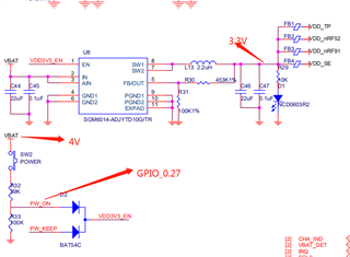
Here VBAT is 4V,PW_ON is connecting to the nrf9160 p0.27 pin.

As the bleeder circuit shows,when SW2 push ,PW_ON voltage should be 4*100/139 ≈ 2.8V,this will enable the power_ic to output 3.3V voltage 

to make the system power on .

However when PW_ON connecte to P0.27,the PW_ON voltage come to 1V which couldn't enable the power_ic.

I think this is probably because the resistance in parallel is causing the voltage divider to work abnormally,so I connect a 100K resistance between PW_ON 

and P0.27 pin , and it works fine.

I want to know which status the nrf9160 gpio in before system power on ? In this case ,should we only to change the bleeder circuit resistance value ?

Brs,

Lemon

Parents Reply
  • Hi,


    lemon said:

    The firmware is the factory code,and haven't been reprogram.

    If I connected the P0.27 to PW_ON,nRF91 couldn't power on, as the VDD3.3_EN cann't enable 

    the power IC to power the system on.

    I guess there is about 13K resistance at P0.27 so that can be 1V .

    The nRF is unpowered at this point in time? If so, this is a flaw in your schematic.

    By applying voltage directly to a GPIO when the nRF is unpowered, you are powering it through the ESD protection inside the nRF.

    By connecting a 100k series resistor, you are restriction the current flow through the unpowered GPIO, and the circuit runs as initially intended.


    Kind regards,

    Håkon

Children
Related