I'm using <TWI Scanner> example on nRF52 DK to find my sensor's address.
According to the sensor datasheet, the sensor's address is 0x21. However, <TWI Scanner> finds the address at 0x20.
Any idea, please?
I'm using <TWI Scanner> example on nRF52 DK to find my sensor's address.
According to the sensor datasheet, the sensor's address is 0x21. However, <TWI Scanner> finds the address at 0x20.
Any idea, please?
Hi Einar, thank you very much for ur help.
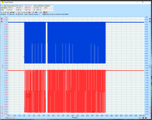
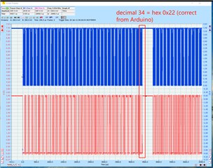
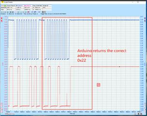
For Arduino UNO, I used I2C to scan my sensor. Here are the plots of SDA (blue) and SCL (red).
Image 1: you could see the Arduino scans 127 I2C addresses.
Image 2: you could see for the 34th address (0x22), Arduino detects the sensor, which is correct.
Image 3: more detailed 34th address SDA and SCL signals.
It looks correct on Arduino.


Here is what I did on nRF52 DK:
1. Use one 4.7k ohm pull-up resistors for SDA and SCL respectively
2. Connect nRF52 detect pin to GND.
3. compile and run <TWI scanner> code.
I found that my nRF52 scans the other devices (e.g. Arduino UNO) show the I2C address is 0x20 as well. It seems like the nRF52 returned I2C address doesn't change.
Since Arduino UNO can detect the sensor at the correct address, I suspect that it's the issue of nRF52.
Thanks, Einar
Hi,
Thank you for the plots and info. This is a bit of a mystery, to be honest. I will look more into it tomorrow and get back to you.
Update.
Now the PuTTY shows an unknown address.
<info> app: TWI device detected at address 0x20.
<info> app: TWI device detected at address 0x22.
However, I only have 1 salve device, which is 0x22.
Any idea why there is 0x20, please?
According to the datasheet of my sensor, its I2C address should be 0x22. I only have 1 slave device.
What I found is if I define the correct TWI address in <TWI sensor> code and run it, then <TWI scanner> could find 2 addresses.
<info> app: TWI enabled
<info> app: TWI device detected at address 0x20.
<info> app: TWI device detected at address 0x22.
However, if I clean the solution, then run the <TWI scanner> again, it can only detect 0x20 address (no idea why I have this address).
Note: my sensor requires a command (0x3608) to enter the continuous data reading mode. This command is unspecified in <TWI scanner> example. It's specified in <TWI sensor>.
Question:
1) Why I have a "ghost" address 0x20?
2) Why I must run <TWI sensor> first, then run <TWI scanner>, then I can see 2 addresses (1 address is correct)?
Hi,
I am not able to answer these questions at the moment, unfortunately. However I have ordered a SDP3x EK (EK-P4) so that I can test on my side. I t might take a couple of days before I get it, though. I will let you know when I have been able to test on my side.
Many appreciations, Einar!
Hi, Einar. From Sensirion company official GitHub, it seems like they only support nRF51.
I asked them that SDP3x will support nRF52 or not. And the reply email from Sensirion company says:
No, we don’t support your specific microcontroller. I’m sorry but we don’t have the resources to customize drivers to every possible platform. We can only provide examples for some of the most common platforms.
Since I'm new to nRF52, does that mean it's impossible to get SDP31 measurements via nRF52 over TWI, pls?
What modifications should I make to let nRF52 get SDP31 measurements over TWI, pls?
Thanks
Hi,
StevenW807 said:Since I'm new to nRF52, does that mean it's impossible to get SDP31 measurements via nRF52 over TWI, pls?
No, it does not mean that. Almost any I2C device should be compatible with the nRF52, it is just that you need to write the driver for it yourself. That should be built on top of the TWI driver or some of the TWI libraries in the nRF5 SDK. It is generally the case that you have to do this yourself.
StevenW807 said:What modifications should I make to let nRF52 get SDP31 measurements over TWI, pls?
I have no experience with tee SDP31. But if you have a driver for the nRF51 which is fairly recent, then porting this to a new nRF5 SDK supporting the nRF52 should be quite simple. We still need to figure out the problem of basic I2C/TWI communication first, though. As mentioned I have ordered the devices and will have a look at that once I get it (it should be right around the corner now).