This post is older than 2 years and might not be relevant anymore
More Info: Consider searching for newer posts

nrf52840 spi miso and transfer not working

hello Nordic

i am working with nrf52840 dev board, sdk 16.0, based on the peripheral app_ble_blinky example.

i have 2 spi comms, one twi, and use rtc, app timer and hfclk timer. so far so good

i check the first spi which is SPI1 (TWI taks the '0') (the other spi will be SPI2)

i don't get what i expect on the MISO line 
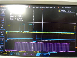
yellow line -CS

light blue line - MOSI

blue line - MISO (number 4 if you can see the number)

purple line - CLK

few strange things:

1. in my sdk_congif.h file miso is config as pulldown (the slave device declares a tristate for the miso)

// <o> NRFX_SPIM_MISO_PULL_CFG  - MISO pin pull configuration.
 
// <0=> NRF_GPIO_PIN_NOPULL 
// <1=> NRF_GPIO_PIN_PULLDOWN 
// <3=> NRF_GPIO_PIN_PULLUP 

#ifndef NRFX_SPIM_MISO_PULL_CFG
#define NRFX_SPIM_MISO_PULL_CFG 1
#endif

but on the photo it looks like the MISO line is in tristate despite my config definition

2. i whish to read 6 bytes of data from the device but my clock counts for 6 bytes including the 2 transferred bytes why is that ?

here is my code for init and trandfer:

#define ACCELO_COMM_SPI_MOSI  NRF_GPIO_PIN_MAP(0, 12) // p0_12  // (SPI_MOSI)
#define ACCELO_COMM_SPI_MISO  NRF_GPIO_PIN_MAP(0, 14) // p0_14  // (SPI_MISO)
#define ACCELO_COMM_SPI_CS    NRF_GPIO_PIN_MAP(0, 16) // p0_16  // (SPI_CS)
#define ACCELO_COMM_SPI_CLK   NRF_GPIO_PIN_MAP(0, 26) // p0_26  // (SPI_CLK)

 nrf_drv_spi_config_t accelo_spi_config = NRF_DRV_SPI_DEFAULT_CONFIG;
    // comm timer ppi config:

    // spi comm config:
    accelo_spi_config.ss_pin   = ACCELO_COMM_SPI_CS;
    accelo_spi_config.miso_pin = ACCELO_COMM_SPI_MISO;
    accelo_spi_config.mosi_pin = ACCELO_COMM_SPI_MOSI;
    accelo_spi_config.sck_pin  = ACCELO_COMM_SPI_CLK;   
    accelo_spi_config.frequency = NRF_DRV_SPI_FREQ_1M;
    accelo_spi_config.orc = 0x00;
    err_code = nrf_drv_spi_init(&accelo_spi, &accelo_spi_config, accelo_spi_event_handler, NULL);
    APP_ERROR_CHECK(err_code);

#define ACCELO_XYZ_ONE_SAMPLE_SIZE  6

static uint8_t       xyz_sample_buff[ACCELO_XYZ_ONE_SAMPLE_SIZE] = { 0 };
static uint8_t read_xyz_sample[] = { READ_REG_CMD_INIT, REG_XDATA_L_ADDRESS };

if( true == spi_xfer_done ) 
{    
    spi_xfer_done = false;
    memset(xyz_sample_buff, 0, sizeof(xyz_sample_buff));
    err_code = nrf_drv_spi_transfer(&accelo_spi, read_xyz_sample, sizeof(read_xyz_sample), 
                                    xyz_sample_buff, sizeof(xyz_sample_buff));
}

3. there are spikes and no legit data on the miso though the mosi is exactly what i am supposed to send according to device data sheet

4. is it possible to config the SPI to be working with lower voltage, like instead of 3.3v to be working in 2v, or alternatively, to config the low level input/output voltage and high level input/output voltage?

still waiting for reply, in the meantime, i cat the SB6 connecting the led2 to the pin p0_14, it did not help, then i changed the pins MISO to p0_26, and CLK to p0_27 and it seems to help with the back signal. any idea why it does not work with the p0_14 ? also, question 1,2,4 are still relevant

hope to read from you soon 

best regards

Ziv

Parents
  •  Hi there!

    1. What voltage do you measure on the pin? I tried measuring with and without a pulldown on MISO and saw a clear difference. The former was about 0V, the latter was floating around some hundred mV. 
    2. I don't think I understand you correctly here. Are you reading more or less data than what you pass as the size parameter?
    3.  Pin 0.14 is used as LED1 on the Devkit. Try cutting the board and avoid initializing the bsp module in your code.
    4. The SPI voltage that is used is VDD. So you need to configure VDD within the operating conditions.

    regards

    Jared

  • Hi Jared

    1. 

    What voltage do you measure on the pin?

    as shown in the picture the v i am seeing is tristate which means a little above 1v at all time, except the time when MISO appears to go to zero when transmitting, so i guess a general question first would be

    - does the pulldown should pull the pin only when there is a clock and chip select is low or does it pulled down all the time ?

    relevant question is that i see the MISO pin remains in tristate even when there is a clock, so maybe my config of pulldown is not done correctly, i am using the sdk_congif.h to define it though id i try going to declaration i get to an old config (i never understand this) ?

    2. 

    I don't think I understand you correctly here

    i use this call :

    err_code = nrf_drv_spi_transfer(&accelo_spi, read_xyz_sample, sizeof(read_xyz_sample), 
                                        xyz_sample_buff, sizeof(xyz_sample_buff));
                                        
    // size of "read_xyz_sample" is 2 bytes
    // size of "xyz_sample_buff" is 6 bytes
    
    // i get clock for total of 6 bytes instead of 8

    i get a clock for 6 bytes instead of 8 (2 bytes for read command, 6 bytes for what i whish to receive ), why is that ? what do i need to change in my configuration or call to get the 6 bytes i whish to receive ?

    3. 

    Try cutting the board and avoid initializing the bsp module in your code.
    i cat the SB6 connecting the led2 to the pin p0_14, it did not help, then i changed the pins MISO to p0_26, and CLK to p0_27 and it seems to help with the back signal. any idea why it does not work with the p0_14

    i also avoided initializing the leds and buttons, so the question remains, why does it work perfectly on another pin and p0_14 just wont work correctly, seems like the spi slave can't raise from 0 to 1 like its overloaded for some reason

    4. if i reconfigure the VDD it will affect all other components in the system, like other SPI instances, TWI and more, am i correct ? or is there a way to configure just one VDD output ?

    hope to read from you soon

    best regards

    Ziv

Reply
  • Hi Jared

    1. 

    What voltage do you measure on the pin?

    as shown in the picture the v i am seeing is tristate which means a little above 1v at all time, except the time when MISO appears to go to zero when transmitting, so i guess a general question first would be

    - does the pulldown should pull the pin only when there is a clock and chip select is low or does it pulled down all the time ?

    relevant question is that i see the MISO pin remains in tristate even when there is a clock, so maybe my config of pulldown is not done correctly, i am using the sdk_congif.h to define it though id i try going to declaration i get to an old config (i never understand this) ?

    2. 

    I don't think I understand you correctly here

    i use this call :

    err_code = nrf_drv_spi_transfer(&accelo_spi, read_xyz_sample, sizeof(read_xyz_sample), 
                                        xyz_sample_buff, sizeof(xyz_sample_buff));
                                        
    // size of "read_xyz_sample" is 2 bytes
    // size of "xyz_sample_buff" is 6 bytes
    
    // i get clock for total of 6 bytes instead of 8

    i get a clock for 6 bytes instead of 8 (2 bytes for read command, 6 bytes for what i whish to receive ), why is that ? what do i need to change in my configuration or call to get the 6 bytes i whish to receive ?

    3. 

    Try cutting the board and avoid initializing the bsp module in your code.
    i cat the SB6 connecting the led2 to the pin p0_14, it did not help, then i changed the pins MISO to p0_26, and CLK to p0_27 and it seems to help with the back signal. any idea why it does not work with the p0_14

    i also avoided initializing the leds and buttons, so the question remains, why does it work perfectly on another pin and p0_14 just wont work correctly, seems like the spi slave can't raise from 0 to 1 like its overloaded for some reason

    4. if i reconfigure the VDD it will affect all other components in the system, like other SPI instances, TWI and more, am i correct ? or is there a way to configure just one VDD output ?

    hope to read from you soon

    best regards

    Ziv

Children
  • Hi.

    I did some tests on the DK and I was indeed able to use Pin 0.14 after cutting the Solder bridge 6 and removing the initializing of the BSP module. I tested it by setting up one board with the SPIS example, and another with the SPI master example with P0.14 as MISO. I was therefore not able to reproduce your issue.  Also, I tested the pulldown feature and it also worked, it pulled the signal low the whole time as expected. There might be some issues introduced by the slave that you're using, could you try to replicate my setup and test by using an additional nRF52 DK as a slave?


    ziv123 said:

    4. if i reconfigure the VDD it will affect all other components in the system, like other SPI instances, TWI and more, am i correct ? or is there a way to configure just one VDD output ?

     Yes, you're correct. All the peripherals will then be affected, there is no way really to separate the voltage domain of the peripherals.

    ziv123 said:

    i get a clock for 6 bytes instead of 8 (2 bytes for read command, 6 bytes for what i whish to receive ), why is that ? what do i need to change in my configuration or call to get the 6 bytes i whish to receive ?

     A SPI transaction is driven by the Master, and uses a shift register scheme. It will therefore end as soon as the Master is done sending data. You could try filling the tx buffer with "dummy data" so that it's the same size as the receive buffer.

    regards

    Jared 

Related