This post is older than 2 years and might not be relevant anymore
More Info: Consider searching for newer posts

How to measure Battery state using VDDH on NRF52840?

Hello,

I am new user for the Nordic NRF528400 microcontroller.
I am working on a project that is using the 8 channels of ADCs to get data from sensors. The system is powered by an external battery and it is necessary to know its status at all times in order to control the system to be powered by the battery or it is necessary to connect the charger.
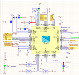
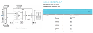
I searched in the microcontroller datasheet and on Nordic dev zone; I found that even if the 8 channels of the ADC are used, we can use the VDDH pin of the µC (capture diagram_block)

My concern is how I can set the reference voltage? Can I connect VDDH directly to the battery and do I need to add elements like resistors or capacitors?

Cordially.

Parents
  • Hello Karl,
    Thank you for your feedback.
    When I mentioned the 8 channels of the ADC are used, I wanted to say that the channels AIN0,..., AIN7 are already connected to some sensors.
    So I would like to know how can I use the VDDH pin of NRF528400 microcontroller to measure the state of an extern battery?

  • A_Has said:
    Thank you for your feedback.

    No problem at all, I am happy to help!

    A_Has said:
    When I mentioned the 8 channels of the ADC are used, I wanted to say that the channels AIN0,..., AIN7 are already connected to some sensors.
    So I would like to know how can I use the VDDH pin of NRF528400 microcontroller to measure the state of an extern battery?

    Ah, then it seems I have misunderstood your last question. 
    A SAADC channel can be connected directly to the VDDH internally, through setting the channels PSEL to 0x0D, no external circuitry needed.
    Same goes for the VDD bus.

    Could you confirm for me which power supply configuration you are using for your device? And that by state, you mean to ask about the voltage level presumably connected to the VDDH pin of the nRF52840?

    Best regards,
    Karl

  • Thank you for availability and your feedback.
    The power supply I want to use is 3.3V on the NRF528400 microcontroller.  

    I want to connect the VDDH pin to an external battery of a type of Li-ion Polymer Battery (Model:UFX251416, Capacity:35mAh).
    For the state, I need to check the battery's state to switch, when it is necessary, to a charger (STBC15QTR).
    Cordially.

  • A_Has said:
    Thank you for availability and your feedback.

    No problem at all, I am happy to help!

    A_Has said:
    I want to connect the VDDH pin to an external battery of a type of Li-ion Polymer Battery (Model:UFX251416, Capacity:35mAh).

    What is the operational voltage range of this particular battery?
    I am unable to find a datasheet the particular part number you reference.
    From your schematic it seems that you will operate in Normal Voltage Mode - since you have shorted VDD and VDDH - which means that the VDD supply must never exceed 3.6V.

    A_Has said:
    The power supply I want to use is 3.3V on the NRF528400 microcontroller. 

    I am assuming that this means that your VDD supply will be a constant 3.3V, regulated somewhere else before being supplied to the nRF52840. However, your wording is a little ambiguous here, so if you could please confirm whether this is the case, that would be great.
    My alternate reading of this is that you intend to use the onboard buck regulator to realize the 3.3 V supply. If this is the case, I would need to know the operational voltage range of the intended battery before I can give any comment.

    Furthermore, I also notice that you are using lower-than-recommended values for your VDD decoupling capacitors. Is there a reason for this?

    Best regards,
    Karl

  • Thank you for your feedback.
    This is the battery datasheet.

    Battery_251416(35mAh)_Datasheet.pdf

    I have chosen to use 3.3V as power supply for the NRF52840 microcontroller because the sensors that I am using should be powered by 3V and there are many devices that should be powered in the whole project (Flash memory, charger, sensors, LEDs,......).
    You have mentioned that I am using lower-than-recommended values of VDD decoupling capacitors. Well, I have contacted an electronic engineer and those were what I was suggested. If you have other proposals, I would appreciate it if you can share them with me.

    Cordially.

  • A_Has said:
    Thank you for your feedback.

    No problem at all, I am happy to help.

    A_Has said:
    This is the battery datasheet.

    Thank you for providing this. From the datasheet it states that the normal voltage of the battery is 3.7 V, which means you will have to use high voltage operating mode.

    A_Has said:
    I have chosen to use 3.3V as power supply for the NRF52840 microcontroller because the sensors that I am using should be powered by 3V and there are many devices that should be powered in the whole project (Flash memory, charger, sensors, LEDs,......).

    What will be the peak concurrent current draw from all these external components?
    You can read more about the possibilities for this in the External circuitry supply section of the power documentation

    A_Has said:
    You have mentioned that I am using lower-than-recommended values of VDD decoupling capacitors. Well, I have contacted an electronic engineer and those were what I was suggested.

    Yes, please see the reference circuitry schematics for the nRF52840.
    Your decoupling should match that of the reference circuitry, for optimal performance.
    If you are using TXPOWER less than +5 dbm it is configuration 4 of the reference circuitry that seems like the correct configuration for your application. Since you intend to use a battery voltage corresponding high voltage mode, you will also have to change your VDD/VDDH connection in the diagram screenshot you attached.

    Best regards,
    Karl

Reply Children
No Data
Related