This post is older than 2 years and might not be relevant anymore
More Info: Consider searching for newer posts

Custom PCB nRF9160 Link monitor ports

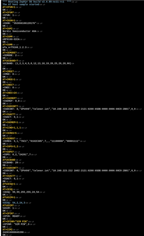
Hi, We have a custom design using an nRF9160.

We can connect and program the device using a jLink though the debug port.

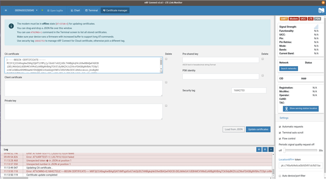
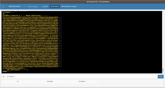
How can we connect the LTE link monitor to the board to transfer AT commands?

Currently our PCB only has access to P0.18 and P0.19 for debug (this can be modified in the next PCB revision).

Can these be re-programmed or are they part of the soft device?

Thanks

Parents
  • Hi Hakon,

    I think your getting a bit confused by the issues, just to clarify...

    I am using our custom PCB with the at_client application installed.

    The application starts and outputs: 

    *** Booting Zephyr OS build v2.4.99-ncs1 ***
    The AT host sample started

    I am using another terminal, not LTE link monitor and AT commands are getting to the nRF

    The problem is the nRF is not responding to AT commands.

    I have modified: nrf9160_nrf9160ns.overlay, CMakeLists.txt, spm.conf and nrf9160_nrf9160.overlay in /nrf/samples/spm

    Please see attached, also attached is our project.

    Thanks

    Ian


    at_client (2).zip


    0066.nrf9160dk_nrf9160.overlay

    #
    # Copyright (c) 2018 Nordic Semiconductor
    #
    # SPDX-License-Identifier: LicenseRef-Nordic-5-Clause
    #
    
    cmake_minimum_required(VERSION 3.13.1)
    
    if (EXISTS "${CMAKE_CURRENT_SOURCE_DIR}/spm.conf")
      set(spm_CONF_FILE
        prj.conf
        ${CMAKE_CURRENT_LIST_DIR}/spm.conf
      )
    endif()
    
    if (EXISTS "${CMAKE_CURRENT_SOURCE_DIR}/mcuboot.conf")
      set(mcuboot_CONF_FILE
        prj.conf
        ${CMAKE_CURRENT_LIST_DIR}/mcuboot.conf
      )
    endif()
    
    if (EXISTS "${CMAKE_CURRENT_SOURCE_DIR}/${BOARD}.overlay")
      set(mcuboot_DTC_OVERLAY_FILE "${CMAKE_CURRENT_SOURCE_DIR}/${BOARD}.overlay")
      set(spm_DTC_OVERLAY_FILE "${CMAKE_CURRENT_SOURCE_DIR}/${BOARD}.overlay")
    endif()
    
    find_package(Zephyr REQUIRED HINTS $ENV{ZEPHYR_BASE})
    project(NONE)
    
    # NORDIC SDK APP START
    target_sources(app PRIVATE src/main.c)
    # NORDIC SDK APP END
    
    spm.conf7652.nrf9160dk_nrf9160ns.overlay

  • Hi Ian,


    My apologies for misunderstanding.

    Yano said:

    I think your getting a bit confused by the issues, just to clarify...

    I am using our custom PCB with the at_client application installed.

    The application starts and outputs: 

    *** Booting Zephyr OS build v2.4.99-ncs1 ***
    The AT host sample started

    I am using another terminal, not LTE link monitor and AT commands are getting to the nRF

    The problem is the nRF is not responding to AT commands.

    I have modified: nrf9160_nrf9160ns.overlay, CMakeLists.txt, spm.conf and nrf9160_nrf9160.overlay in /nrf/samples/spm

    Please see attached, also attached is our project.

    I tested at_client (2).zip, with the merged.hex located in the build-folder (ie. the same .hex as you're currently using).

    I can confirm that I am able to get an output on P0.19 (TXD seen from nRF) and I am also able to send AT commands via a terminal on GPIO P0.18 (RXD, seen from nRF)

    I tested this by manually connecting P0.19/P0.18 to the nRF9160-DKs SEGGER ICs host UART pins.

    Here's my output from when issuing "AT+CLAC" to list all available AT commands (no echo in the terminal):

    *** Booting Zephyr OS build v2.4.99-ncs1  ***
    The AT host sample started
    AT+CFUN
    AT+COPS
    AT%COPS
    AT+CGDCONT
    AT+CGACT
    AT+CEMODE
    AT+CGATT
    AT+CGEQOSRDP
    AT+CPINR
    AT+CPIN
    AT+CPSMS
    AT+CEDRXS
    AT%XPTW
    AT+CEDRXRDP
    AT+CEREG
    AT%XNEWCID
    AT%XGETPDNID
    AT+CLAC
    AT+CMEE
    AT+CGMI
    AT+CGMM
    AT+CGMR
    AT+CGSN
    AT+CIMI
    AT+CSCON
    AT+CMGS
    AT+CNMA
    AT+CNMI
    AT+CMGF
    AT+CPMS
    AT+CGSMS
    AT%XSMMA
    AT%CMNG
    AT+CNEC
    AT+CGEREP
    AT%CESQ
    AT%XPCO
    AT+CESQ
    AT%XSIM
    AT%XBANDLOCK
    AT+CGPIAF
    AT+CPAS
    AT+COPN
    AT+CSQ
    AT+CEER
    AT+CNUM
    AT+CRSM
    AT+CIND
    AT+CLCK
    AT+CPWD
    AT%XCBAND
    AT+CGPADDR
    AT+CGCONTRDP
    AT%NBRGRSRP
    AT+CSIM
    AT%XOPNAME
    AT%XTIME
    AT%XRAI
    AT%XCONNSTAT
    AT+CEPPI
    AT%XDATAPRFL
    AT%XMAGPIO
    AT%XANTDETMAGPIO
    AT%XMIPIRFFEDEV
    AT%XMIPIRFFECTRL
    AT%XCOEX0
    AT%XANTCFG
    AT%XEMPR
    AT%XSUDO
    AT%XPMNG
    AT%XRFTEST
    AT%XAPNCLASS
    AT%XTEMPHIGHLVL
    AT%XTEMP
    AT%XPRODDONE
    AT%XMODEMTRACE
    AT%XEPCO
    AT%XVBATLOWLVL
    AT%XVBATLVL
    AT%XVBAT
    AT+CCLK
    AT%CCLK
    AT%XIPV6FAIL
    AT%XUSIMLCK
    AT%XOPERID
    AT%XSMSFALLBACK
    AT%XSYSTEMMODE
    AT%XSNRSQ
    AT+CGAUTH
    AT%XMONITOR
    AT%SHORTSWVER
    AT%HWVERSION
    AT%XMODEMUUID
    AT%XICCID
    AT+ODISNTF
    AT+ODIS
    AT%ODIS
    AT%XNETTIME
    AT%XDEEPSEARCH
    AT%XFILEWRITE
    AT+CEINFO
    AT%XPDNCFG
    AT+CSODCP
    AT%XDATASTOP
    AT%XAPNSTATUS
    AT%XPOFWARN
    OK


    The firmware itself seems to run as-expected wrt. using UART with P0.18 and P0.19.

    What is the VDD_GPIO level on your custom board? Could it be that there is a mismatch between the voltage levels on your USB/UART and the nRF?


    Kind regards,

    Håkon

  • Hi Håkon,

    I was just thinking the same!

    Before I read your post I had just checked it.

    I had modified our USB interface to work with 1.8V and of course our hardware is working at 3.3V

    So it worked fine with the DK but not our hardware.

    So I am getting a response!! Slight smile

    A few more questions:

    1. Is there a way to start the AT client in code, so the test house don't have to use a terminal to start it?

    2. I need to see if it is working (e.g. getting responses back from cells) is there an AT command I can use?

    3. Do I need the overlay in the SPM (secure boot) project?

    Sorry for hassling you I'm under a lot of pressure to get this into test tomorrow.

    Thanks

    Ian

  • Hi Ian,


    Yano said:
    Sorry for hassling you I'm under a lot of pressure to get this into test tomorrow.

    Don't worry about this. That is no problem at all, and I'm very happy to help you out.


    Yano said:

    I had modified our USB interface to work with 1.8V and of course our hardware is working at 3.3V

    So it worked fine with the DK but not our hardware.

    So I am getting a response!!

    This is great to hear! Just to confirm: You can now communicate in LTE Link Monitor with your own hardware, and the FTDI USB/UART bridge?


    Yano said:
    1. Is there a way to start the AT client in code, so the test house don't have to use a terminal to start it?

     It is possible to hard code certain AT commands, but you usually do not want to do this, as you want to keep the firmware as versatile as possible, in case the test house needs to do certain RF testing on other bands etc.

    The easiest thing is to use the at_client, and manually call the AT commands, for instance AT%XRFTEST for RF PHY evaluation:

    https://infocenter.nordicsemi.com/topic/ref_at_commands/REF/at_commands/production_test/xrftest_set.html?cp=2_1_10_1_0


    Yano said:
    2. I need to see if it is working (e.g. getting responses back from cells) is there an AT command I can use?

    From the LTE Network? AT+CEREG can give you the network registration status: https://infocenter.nordicsemi.com/topic/ref_at_commands/REF/at_commands/nw_service/cereg.html?cp=2_1_7_9


    Yano said:
    3. Do I need the overlay in the SPM (secure boot) project?

     This is not directly needed. By adjusting your at_client/CMakeLists.txt file and adding this:

    if (EXISTS "${CMAKE_CURRENT_SOURCE_DIR}/${BOARD}.overlay")
      set(mcuboot_DTC_OVERLAY_FILE "${CMAKE_CURRENT_SOURCE_DIR}/${BOARD}.overlay")
      set(spm_DTC_OVERLAY_FILE "${CMAKE_CURRENT_SOURCE_DIR}/${BOARD}.overlay")
    endif()


    Then you are telling the multi-build system to also include your $(BOARD).overlay file to be applied for spm and potentially mcuboot (if present).

    This is the equivalent operation to manually going into the spm project and pasting your $(BOARD-NOT_NS).overlay file into that directory.


    As your at_client is setup at this moment, it successfully setup the uart pins to P0.18/P0.19.


    Kind regards,

    Håkon

  • Hi Hakon,

    It's been a bit stressful with this deadline, thanks for all you help!

    I can't talk to our device through LTE Link Monitor with our own hardware, to do that I need to use a terminal application.

    First of all I've moved to a Prolific USB/UART bridge instead of the FTDI one (for now) but it was the same with that bridge.

    Here is a test sequence:

    1. start up our terminal application (Tera Term VT) and connect to com 9 (Prolific).

    2. Power cycle the board.

    3. Get boot message on screen.

    4. Send AT command and get OK response.

    5. Close Tera Term.

    6. Connect to same com 9 using LTE monitor.

    7. Send AT command get timeout error

    8. Power cycle the board.

    9. Get boot message

    10. Send AT command get timeout error again.

    11. Close device in LTE monitor

    12. Open Tera Term back up and connect to com 9

    13. Send AT command and get OK response.

    14. Power cycle the board.

    15. Get boot message on screen.

    16. Send AT command and get OK response.

    17. Close Tera Term.

    I've scoped it and I can confirm LTE link monitor is not sending commands but Tera Term is?!

    I can't be sure but I think there's something odd happening with LTE Link monitor (V1.1.10). BTW Auto device/port filter is not selected.

    Any ideas?

    Ian

Reply
  • Hi Hakon,

    It's been a bit stressful with this deadline, thanks for all you help!

    I can't talk to our device through LTE Link Monitor with our own hardware, to do that I need to use a terminal application.

    First of all I've moved to a Prolific USB/UART bridge instead of the FTDI one (for now) but it was the same with that bridge.

    Here is a test sequence:

    1. start up our terminal application (Tera Term VT) and connect to com 9 (Prolific).

    2. Power cycle the board.

    3. Get boot message on screen.

    4. Send AT command and get OK response.

    5. Close Tera Term.

    6. Connect to same com 9 using LTE monitor.

    7. Send AT command get timeout error

    8. Power cycle the board.

    9. Get boot message

    10. Send AT command get timeout error again.

    11. Close device in LTE monitor

    12. Open Tera Term back up and connect to com 9

    13. Send AT command and get OK response.

    14. Power cycle the board.

    15. Get boot message on screen.

    16. Send AT command and get OK response.

    17. Close Tera Term.

    I've scoped it and I can confirm LTE link monitor is not sending commands but Tera Term is?!

    I can't be sure but I think there's something odd happening with LTE Link monitor (V1.1.10). BTW Auto device/port filter is not selected.

    Any ideas?

    Ian

Children
  • Hi Ian,


    Yano said:
    I've scoped it and I can confirm LTE link monitor is not sending commands but Tera Term is?!
    Yano said:
    First of all I've moved to a Prolific USB/UART bridge instead of the FTDI one (for now) but it was the same with that bridge.

    It is very good to hear that the usb/uart adapters themselves work with various other terminal programs.

     I have created a bug internally on this matter. based on the test procedure that you have gone through, everything points to the LTE Link Monitor not properly handling sending data from the PC -> USB/UART adapter.


    The best option as of now, is to use a generic terminal application to issue the specific AT commands required by the test house (usually AT%XRFTEST, and maybe a test to connect to a network via AT+CFUN=1).


    Please let me know if you run into any issues with the testing procedure.


    Kind regards,

    Håkon

  • Hi Håkon, 

    I think I'm OK for the RED testing (now starting Monday) but I also need to get certs into our hardware.

    Is there a way to do this using a standard serial terminal?

    Could we use USB bridge on an nRF9160-DK and wire it to our hardware and if so what way could we wire it, we have not problem modifying one (cutting tracks etc.).

    Also is there a document on the pin re-assignment process (.overlay etc) we had to do? I would like to fully understand the script used.

    Thanks

    Ian  

  • Hi Ian,


    Yano said:

    Is there a way to do this using a standard serial terminal?

    Could we use USB bridge on an nRF9160-DK and wire it to our hardware and if so what way could we wire it, we have not problem modifying one (cutting tracks etc.).

    Also is there a document on the pin re-assignment process (.overlay etc) we had to do? I would like to fully understand the script used.

    I think you are over-thinking what LTE Link Monitor provides. I agree that it is helpful for the automatic response attach after issuing AT+CFUN=1, but most of this is not strictly required when going 3GPP testing, as such tests are usually carried out from the LTE tester point of view. Any RF PHY evaluating specific command isn't parsed in LTE LinkMonitor either.

    LTE Link Monitor is a terminal, similar to teraterm/realterm/putty, that can parse specific AT command response. There's strictly no need to use it, but it helps  wrt. what it "automatically" issues if you have "automatic requests" enabled, and issue a "AT+CFUN?" and parse the information provided by the different AT commands (your IP, RSRP, network status).


    For issuing AT%XRFTEST, the LTE Link Monitor does not give you any parsed output, expect color highlighting.


    If you are interested in the sequence that it provides when doing automatic requests, here's an example of that:

    *** Booting Zephyr OS build v2.4.99-ncs1-rc1  ***
    The AT host sample started
    AT+CFUN=1
    OK
    AT+CFUN?
    +CFUN: 1
    OK
    AT+CGSN=1
    +CGSN: "352656106120176"
    OK
    AT+CGMI
    Nordic Semiconductor ASA
    OK
    AT+CGMM
    nRF9160-SICA
    OK
    AT+CGMR
    mfw_nrf9160_1.2.3
    OK
    AT+CEMODE?
    +CEMODE: 2
    OK
    AT%XCBAND=?
    %XCBAND: (1,2,3,4,5,8,12,13,18,19,20,25,26,28,66)
    OK
    AT+CMEE?
    +CMEE: 0
    OK
    AT+CMEE=1
    OK
    AT+CNEC?
    +CNEC: 0
    OK
    AT+CNEC=24
    OK
    AT+CGEREP?
    +CGEREP: 0,0
    OK
    AT+CGDCONT?
    +CGDCONT: 0,"IPV4V6","telenor.iot","10.240.223.212 2A02:2121:0208:65DB:0000:0006:08C9:2B01",0,0
    OK
    AT+CGACT?
    +CGACT: 0,1
    OK
    AT+CGEREP=1
    OK
    AT+CIND=1,1,1
    OK
    AT+CEREG=5
    OK
    AT+CEREG?
    +CEREG: 5,1,"76C1","0102C305",7,,,"11100000","00001111"
    OK
    AT+COPS=3,2
    OK
    AT+COPS?+COPS: 0,2,"24201",7
    OK
    AT%XCBAND%XCBAND: 20
    OK
    AT+CGDCONT?
    +CGDCONT: 0,"IPV4V6","telenor.iot","10.240.223.212 2A02:2121:0208:65DB:0000:0006:08C9:2B01",0,0
    OK
    AT+CGACT?
    +CGACT: 0,1
    OK
    AT%CESQ=1
    OK
    AT+CESQ
    +CESQ: 99,99,255,255,24,54
    OK
    AT%XSIM=1
    OK
    %CESQ: 54,2,24,3
    AT%XSIM?
    %XSIM: 1
    OK
    AT+CPIN?
    +CPIN: READY
    OK
    AT+CPINR="SIM PIN"
    +CPINR: "SIM PIN",3
    OK
    AT+CIMI
    242016000045390
    OK

     Picture:


    The above commands are mostly meta-data, and you can check out the documentation for each of them in the AT commands document:

    https://infocenter.nordicsemi.com/topic/ref_at_commands/REF/at_commands/intro.html?cp=2_1


    Kind regards,

    Håkon

  • Hi Hakon,

    Any update on this?

     I have created a bug internally on this matter. based on the test procedure that you have gone through, everything points to the LTE Link Monitor not properly handling sending data from the PC -> USB/UART adapter.

    Not being able to upload certs is hampering us. If there was a way to do it in code it would be great.

    Thanks

    Ian

  • Hi Ian,


    My deepest apologies for the behavior you're seeing here. It is not yet fixed in nRF connect for desktop.


    In firmware, you can use the API "modem_key_mgmt_write" to write certificates, similar to how it is done in the aws_fota sample:

    https://developer.nordicsemi.com/nRF_Connect_SDK/doc/latest/nrf/samples/nrf9160/aws_fota/README.html#updating-the-certificates


    Writing the certificate in firmware require that you put the certificate into "C format".

    If we take the AWS root CA as an example, which you can find here:

    https://www.amazontrust.com/repository/AmazonRootCA1.pem

    This holds, in ascii:

    -----BEGIN CERTIFICATE-----
    MIIDQTCCAimgAwIBAgITBmyfz5m/jAo54vB4ikPmljZbyjANBgkqhkiG9w0BAQsF
    ADA5MQswCQYDVQQGEwJVUzEPMA0GA1UEChMGQW1hem9uMRkwFwYDVQQDExBBbWF6
    b24gUm9vdCBDQSAxMB4XDTE1MDUyNjAwMDAwMFoXDTM4MDExNzAwMDAwMFowOTEL
    MAkGA1UEBhMCVVMxDzANBgNVBAoTBkFtYXpvbjEZMBcGA1UEAxMQQW1hem9uIFJv
    b3QgQ0EgMTCCASIwDQYJKoZIhvcNAQEBBQADggEPADCCAQoCggEBALJ4gHHKeNXj
    ca9HgFB0fW7Y14h29Jlo91ghYPl0hAEvrAIthtOgQ3pOsqTQNroBvo3bSMgHFzZM
    9O6II8c+6zf1tRn4SWiw3te5djgdYZ6k/oI2peVKVuRF4fn9tBb6dNqcmzU5L/qw
    IFAGbHrQgLKm+a/sRxmPUDgH3KKHOVj4utWp+UhnMJbulHheb4mjUcAwhmahRWa6
    VOujw5H5SNz/0egwLX0tdHA114gk957EWW67c4cX8jJGKLhD+rcdqsq08p8kDi1L
    93FcXmn/6pUCyziKrlA4b9v7LWIbxcceVOF34GfID5yHI9Y/QCB/IIDEgEw+OyQm
    jgSubJrIqg0CAwEAAaNCMEAwDwYDVR0TAQH/BAUwAwEB/zAOBgNVHQ8BAf8EBAMC
    AYYwHQYDVR0OBBYEFIQYzIU07LwMlJQuCFmcx7IQTgoIMA0GCSqGSIb3DQEBCwUA
    A4IBAQCY8jdaQZChGsV2USggNiMOruYou6r4lK5IpDB/G/wkjUu0yKGX9rbxenDI
    U5PMCCjjmCXPI6T53iHTfIUJrU6adTrCC2qJeHZERxhlbI1Bjjt/msv0tadQ1wUs
    N+gDS63pYaACbvXy8MWy7Vu33PqUXHeeE6V/Uq2V8viTO96LXFvKWlJbYK8U90vv
    o/ufQJVtMVT8QtPHRh8jrdkPSHCa2XV4cdFyQzR1bldZwgJcJmApzyMZFo6IQ6XU
    5MsI+yMRQ+hDKXJioaldXgjUkK642M4UwtBV8ob2xJNDd2ZhwLnoQdeXeGADbkpy
    rqXRfboQnoZsG4q5WTP468SQvvG5
    -----END CERTIFICATE-----

    To put this into a C format, we need to add line ending and place it into a array:

    "-----BEGIN CERTIFICATE-----\n" \
    "MIIDQTCCAimgAwIBAgITBmyfz5m/jAo54vB4ikPmljZbyjANBgkqhkiG9w0BAQsF\n" \
    "ADA5MQswCQYDVQQGEwJVUzEPMA0GA1UEChMGQW1hem9uMRkwFwYDVQQDExBBbWF6\n" \
    "b24gUm9vdCBDQSAxMB4XDTE1MDUyNjAwMDAwMFoXDTM4MDExNzAwMDAwMFowOTEL\n" \
    "MAkGA1UEBhMCVVMxDzANBgNVBAoTBkFtYXpvbjEZMBcGA1UEAxMQQW1hem9uIFJv\n" \
    "b3QgQ0EgMTCCASIwDQYJKoZIhvcNAQEBBQADggEPADCCAQoCggEBALJ4gHHKeNXj\n" \
    "ca9HgFB0fW7Y14h29Jlo91ghYPl0hAEvrAIthtOgQ3pOsqTQNroBvo3bSMgHFzZM\n" \
    "9O6II8c+6zf1tRn4SWiw3te5djgdYZ6k/oI2peVKVuRF4fn9tBb6dNqcmzU5L/qw\n" \
    "IFAGbHrQgLKm+a/sRxmPUDgH3KKHOVj4utWp+UhnMJbulHheb4mjUcAwhmahRWa6\n" \
    "VOujw5H5SNz/0egwLX0tdHA114gk957EWW67c4cX8jJGKLhD+rcdqsq08p8kDi1L\n" \
    "93FcXmn/6pUCyziKrlA4b9v7LWIbxcceVOF34GfID5yHI9Y/QCB/IIDEgEw+OyQm\n" \
    "jgSubJrIqg0CAwEAAaNCMEAwDwYDVR0TAQH/BAUwAwEB/zAOBgNVHQ8BAf8EBAMC\n" \
    "AYYwHQYDVR0OBBYEFIQYzIU07LwMlJQuCFmcx7IQTgoIMA0GCSqGSIb3DQEBCwUA\n" \
    "A4IBAQCY8jdaQZChGsV2USggNiMOruYou6r4lK5IpDB/G/wkjUu0yKGX9rbxenDI\n" \
    "U5PMCCjjmCXPI6T53iHTfIUJrU6adTrCC2qJeHZERxhlbI1Bjjt/msv0tadQ1wUs\n" \
    "N+gDS63pYaACbvXy8MWy7Vu33PqUXHeeE6V/Uq2V8viTO96LXFvKWlJbYK8U90vv\n" \
    "o/ufQJVtMVT8QtPHRh8jrdkPSHCa2XV4cdFyQzR1bldZwgJcJmApzyMZFo6IQ6XU\n" \
    "5MsI+yMRQ+hDKXJioaldXgjUkK642M4UwtBV8ob2xJNDd2ZhwLnoQdeXeGADbkpy\n" \
    "rqXRfboQnoZsG4q5WTP468SQvvG5\n" \
    "-----END CERTIFICATE-----\n"


    if you add "#define MY_CA_CERT \" to the above, you can do like this in firmware (before issuing AT+CFUN=1!):

    	err = modem_key_mgmt_write(MY_USED_SEC_TAG,
    				   MODEM_KEY_MGMT_CRED_TYPE_CA_CHAIN,
    				   MY_CA_CERT,
    				   strlen(MY_CA_CERT));
    	if (err) {
    		printk("Failed to provision CA certificate, err %d\n", err);
    		return err;
    	}				   


    The sequence for inputting private (MODEM_KEY_MGMT_CRED_TYPE_PRIVATE_CERT) and public (MODEM_KEY_MGMT_CRED_TYPE_PUBLIC_CERT) is similar to the above.


    Alternative 2:

    Fetch the raw AT command by opening any COM port (any COM port that can be opened in LTE LM will do here) 

    Here I have inputted a CA root:

    This AT cmd has failed to write to my specified security tag.

    However, If I switch to the "terminal" view, I can see the AT command that has been inputted:


    You can also see this in the log if you press the "open log" here:


    Kind regards,

    Håkon

Related