This post is older than 2 years and might not be relevant anymore
More Info: Consider searching for newer posts

Use another nrf52840 to eavesdrop on the master and slave communicating with SPI

My stm32 (as a master) uses SPI to communicate with nrf52840 (as a slave)
When my nrf52840 wants to send data to stm32, it will pull a GPIO to let stm32 generate a GPIO interrupt to read the data transmitted by nrf52840

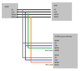
Now I want to use another listen_nrf52840 (as a sniffer) to receive the data transmitted by both of them in parallel.
The SPI pin of my listen_nrf52840 is the same as the SPI slave, but it can only receive data from the master, as shown below

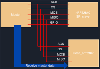
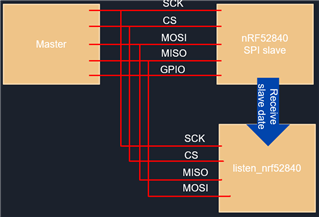
However, when I swap the MOSI and MISO pins of listen_nrf52840, I can receive the data sent by the SPI slave.
As shown below

Kind of like what a logic analyzer is doing

Can I change the pin number of listen_nrf52840 during operation?
Or is there any way for the SPI slave to receive data from another SPI slave and master at the same time ?

Thanks in advanced,

Poyi

Parents
  • Hello,

    I don't know whether you intend to create this as part of a larger application, or if you intend to just create an SPI sniffer. Either way, there is a few challenges that needs some attention.

    The MISO line in an SPI peripheral is an output pin (when the nRF is not the master). Assuming that the SPI is used for bidirectional communication (simultaneously), it would not be possible to connect the two lines together either. So you need two input pins, instead of one input and one output. 

    The SPI doesn't support two inputs like this, unfortunately, so as I see it, you have two options:

    Either, you can bitbang the data lines. This is really not recommended, because it takes a lot of CPU capacity (you require severeal interrupts per byte). At least if you intend to do something else (such as Bluetooth Low Energy) at the same time, this will not work very well. 

    The other option is to use two SPI instances at the same time, and use the MOSI pins for each of them. Connect one to the actuall SPI's MOSI, and the other one to the MISO. So basically, do what you already did, but use two SPI instances, and connect MOSI on each instance to MOSI and MISO on the actual SPI you want to sniff. I think this is your best shot. You have already done half of it.

    Best regards,

    Edvin

Reply
  • Hello,

    I don't know whether you intend to create this as part of a larger application, or if you intend to just create an SPI sniffer. Either way, there is a few challenges that needs some attention.

    The MISO line in an SPI peripheral is an output pin (when the nRF is not the master). Assuming that the SPI is used for bidirectional communication (simultaneously), it would not be possible to connect the two lines together either. So you need two input pins, instead of one input and one output. 

    The SPI doesn't support two inputs like this, unfortunately, so as I see it, you have two options:

    Either, you can bitbang the data lines. This is really not recommended, because it takes a lot of CPU capacity (you require severeal interrupts per byte). At least if you intend to do something else (such as Bluetooth Low Energy) at the same time, this will not work very well. 

    The other option is to use two SPI instances at the same time, and use the MOSI pins for each of them. Connect one to the actuall SPI's MOSI, and the other one to the MISO. So basically, do what you already did, but use two SPI instances, and connect MOSI on each instance to MOSI and MISO on the actual SPI you want to sniff. I think this is your best shot. You have already done half of it.

    Best regards,

    Edvin

Children
  • Hello
    Thanks for your reply
    Open two SPI slaves, I have tried
    But I would like to ask if there is a sample program to open two SPI slaves at once?
    Currently open two at a time, only one will generate an interrupt

    I don't know what to do now
    Below is my code, maybe it will help

    
    #include <stdint.h>
    #include <stdlib.h>
    #include "nrf_drv_spis.h"
    #include <time.h>
    #include <stdbool.h>
    #include <stdio.h>
    #include "radio_config.h"
    #include "nrf_gpio.h"
    #include "nrf_delay.h"
    #include "app_timer.h"
    #include "app_uart.h"
    #include "boards.h"
    #include "bsp.h"
    #include "nordic_common.h"
    #include "nrf_error.h"
    #include "nrf_drv_twis.h"
    #include "string.h"
    #include "nrf_drv_timer.h"
    #include "nrf_drv_gpiote.h"
    #include "nrf_drv_wdt.h"
    
    #define APP_SPIS_CS_PIN 28 
    #define APP_SPIS_MISO_PIN 30 
    #define APP_SPIS_MOSI_PIN 31 
    #define APP_SPIS_SCK_PIN  29
    
    
    #define ONE_SECON   32768
    #define RELOAD      0x6E524635
    #define SLEEP_BIT   0
    #define HALT_BIT    3
    #define WDT_RELOAD  NRF_WDT->RR[0]=RELOAD;
    
    #define APP_TIMER_PRESCALER      0                           /**< Value of the RTC1 PRESCALER register. */
    #define APP_TIMER_OP_QUEUE_SIZE  2                           /**< Size of timer operation queues. */
    #define UART_TX_BUF_SIZE 256                         				 /**< UART TX buffer size. */
    #define UART_RX_BUF_SIZE 256                                 /**< UART RX buffer size. */
    
    #define MAX_BYTES_TX 32
    #define MAX_NUM_DEVICE 10   //MAX=255
    
    
    #define SPIS_INSTANCE 1 /**< SPIS instance index. */
    static const nrf_drv_spis_t spis = NRF_DRV_SPIS_INSTANCE(1);/**< SPIS instance. */
    
    static uint8_t       m_tx_buf[8] = {0};           /**< TX buffer. */
    static uint8_t       m_rx_buf[8] = {0};    /**< RX buffer. */
    static const uint8_t m_length = sizeof(m_tx_buf);        /**< Transfer length. */
    
    //#define SPIS_INSTANCE 0 /**< SPIS instance index. */
    static const nrf_drv_spis_t spis0 = NRF_DRV_SPIS_INSTANCE(0);/**< SPIS instance. */
    
    static uint8_t       m_tx_buf0[8] = {0};           /**< TX buffer. */
    static uint8_t       m_rx_buf0[8] = {0};    /**< RX buffer. */
    static const uint8_t m_length0 = sizeof(m_tx_buf0);        /**< Transfer length. */
    
    static volatile bool spis_xfer_done; /**< Flag used to indicate that SPIS instance completed the transfer. */


    APP_TIMER_DEF(app_timer0);  
    
    
    uint8_t readend_flag =0;
    
    void spis_event_handler1(nrf_drv_spis_event_t event)
    {
    	uint8_t i = 0;
        if (event.evt_type == NRF_DRV_SPIS_XFER_DONE)
        {
    		printf("zzz\r\n");
            spis_xfer_done = true;
    		printf("tx ");
    				for(i = 0 ; i< 8 ; i++)
    				printf("%d ",m_tx_buf[i]);
    			for(i = 0 ; i< 8 ; i++)
    				printf("%d ",m_rx_buf[i]);
    			printf("\r\n");
    		
    		if(m_rx_buf[0] && m_rx_buf[0]!= 255)//52832 rx
    		{
    //		printf("read ");
    //				for(i = 0 ; i< 8 ; i++)
    //				printf("%d ",m_rx_buf[i]);
    //			printf("\r\n");
    			
    			//if((m_rx_buf[0] == 4 || m_rx_buf[0] == 6 || m_rx_buf[0] == 5 || m_rx_buf[0] == 7 ) &&m_rx_buf[1] == Car_id - 'C')
    			if((m_rx_buf[0] == 4 || m_rx_buf[0] == 6 || m_rx_buf[0] == 5 || m_rx_buf[0] == 7 ) || m_rx_buf[1] == Car_id - 'C')
    			{
    					
    				//	
    				
    				if(tmpbuffer[0] == 0 || m_rx_buf[0] != 4)
    				{
    					memcpy(tmpbuffer,m_rx_buf,sizeof(tmpbuffer));
    					//if(m_rx_buf[0] != 4)
    						//nrf_gpio_pin_set(27);	
    					//starttx_flag = 1;//RF TO GATEWAY
    					
    					
    					memset(m_rx_buf,0,8);
    					copydata = 1;
    					
    					
    				}
    			
    				
    			}
    //			printf("read ");
    //				for(i = 0 ; i< 8 ; i++)
    //				printf("%d ",m_rx_buf[i]);
    //			printf("\r\n");
    		readend_flag = 1;
    			
    			//printf("q\r\n");
    		//	nrf_gpio_pin_clear(26);	
    			
    		}
    		else if(m_rx_buf[0] == 255)//52832 tx&& m_rx_buf[0]== 255
    		{
    //			for(i = 0 ; i< 8 ; i++)
    //				printf("%d ",m_tx_buf[i]);
    //			printf("write\r\n");
    			handlepacket = 0;
    			
    			//memset(m_tx_buf,0,8);
    		}
    		//printf(" Transfer completed. Received: %d\r\n",(uint32_t)m_rx_buf[0]);
    		nrf_delay_us(40);
    		nrf_drv_spis_buffers_set(&spis, m_tx_buf, m_length, m_rx_buf, m_length);
    		//nrf_gpio_pin_set(26);	
        }
    	else if (event.evt_type == NRF_DRV_SPIS_BUFFERS_SET_DONE)
        {
    //		printf("test\r\n");
    //		printf("tx ");
    //				for(i = 0 ; i< 8 ; i++)
    //				printf("%d ",m_tx_buf[i]);
    
    //				for(i = 0 ; i< 8 ; i++)
    //				printf("%d ",m_rx_buf[i]);
    //			printf("\r\n");
    
    
    	}
    	else if (event.evt_type == NRF_DRV_SPIS_EVT_TYPE_MAX)
        {
    //		printf("test2\r\n");
    //	
    	}
    }
    
    void spis_event_handler0(nrf_drv_spis_event_t event)
    {
    	uint8_t i = 0;
        if (event.evt_type == NRF_DRV_SPIS_XFER_DONE)
        {
    		printf("AAAAAAA\r\n");
            spis_xfer_done = true;
    		printf("Atx ");
    				for(i = 0 ; i< 8 ; i++)
    				printf("%d ",m_tx_buf0[i]);
    			for(i = 0 ; i< 8 ; i++)
    				printf("%d ",m_rx_buf0[i]);
    			printf("\r\n");
    		
    		if(m_rx_buf0[0] && m_rx_buf0[0]!= 255)//52832 rx
    		{
    //		printf("read ");
    //				for(i = 0 ; i< 8 ; i++)
    //				printf("%d ",m_rx_buf[i]);
    //			printf("\r\n");
    			
    
    		readend_flag = 1;


    		}
    		nrf_delay_us(40);
    		nrf_drv_spis_buffers_set(&spis, m_tx_buf, m_length, m_rx_buf, m_length);
    	}
    }
    
    void clock_initialization()
    {
        /* Start 16 MHz crystal oscillator */
        NRF_CLOCK->EVENTS_HFCLKSTARTED = 0;
        NRF_CLOCK->TASKS_HFCLKSTART    = 1;
    
        /* Wait for the external oscillator to start up */
        while (NRF_CLOCK->EVENTS_HFCLKSTARTED == 0)
        {
            // Do nothing.
        }
    
        /* Start low frequency crystal oscillator for app_timer(used by bsp)*/
        NRF_CLOCK->LFCLKSRC            = (CLOCK_LFCLKSRC_SRC_Xtal << CLOCK_LFCLKSRC_SRC_Pos);
        NRF_CLOCK->EVENTS_LFCLKSTARTED = 0;
        NRF_CLOCK->TASKS_LFCLKSTART    = 1;
    
        while (NRF_CLOCK->EVENTS_LFCLKSTARTED == 0)
        {
            // Do nothing.
        }
    }


    void uart_error_handle(app_uart_evt_t * p_event)
    {
        /*if (p_event->evt_type == APP_UART_COMMUNICATION_ERROR)
        {
            APP_ERROR_HANDLER(p_event->data.error_communication);
        }
        else if (p_event->evt_type == APP_UART_FIFO_ERROR)
        {
            APP_ERROR_HANDLER(p_event->data.error_code);
        }*/
    }


    void UART_init(){
    
    uint32_t err_code;   
    	
    const app_uart_comm_params_t comm_params =
          {
              RX_PIN_NUMBER,
              TX_PIN_NUMBER,
              NULL,
    					NULL,
    					APP_UART_FLOW_CONTROL_DISABLED,
              false,
              UART_BAUDRATE_BAUDRATE_Baud115200
          };
    
     APP_UART_FIFO_INIT(&comm_params,
                             UART_RX_BUF_SIZE,
                             UART_TX_BUF_SIZE,
                             uart_error_handle,
                             APP_IRQ_PRIORITY_LOW,
                             err_code);
    
        APP_ERROR_CHECK(err_code);
    }
    
    
    void gpio_handler(nrf_drv_gpiote_pin_t pin, nrf_gpiote_polarity_t action){
    	//nrf_drv_twis_uninit(&m_twis);
    	//nrf_drv_twis_disable(&m_twis);
    	//NRF52_TWIS_init();
    //	printf("zzz\r\n");
    	//NVIC_SystemReset();
    	
    }
    //static void gpio_init(void)
    //{
    //    ret_code_t err_code;
    
    //    err_code = nrf_drv_gpiote_init();
    //    APP_ERROR_CHECK(err_code);
    //		
    
    //    nrf_drv_gpiote_in_config_t in_config = NRFX_GPIOTE_RAW_CONFIG_IN_SENSE_LOTOHI(true);
    //    in_config.pull = NRF_GPIO_PIN_PULLDOWN;
    
    //    err_code = nrf_drv_gpiote_in_init(11, &in_config, gpio_handler);
    //    APP_ERROR_CHECK(err_code);
    //	nrf_drv_gpiote_in_event_enable(11, true);
    
    //}
    
    void spis_init()
    {
    		
    	nrf_drv_spis_config_t spis_config = NRF_DRV_SPIS_DEFAULT_CONFIG;
    	
    	spis_config.csn_pin               = APP_SPIS_CS_PIN;
        spis_config.miso_pin              = APP_SPIS_MISO_PIN;
        spis_config.mosi_pin              = APP_SPIS_MOSI_PIN;
        spis_config.sck_pin               = APP_SPIS_SCK_PIN;
    	//APP_ERROR_CHECK(nrf_drv_spis_init(&spis, &spis_config, spis_event_handler));
    	nrf_drv_spis_init(&spis, &spis_config, spis_event_handler1);
    	
    }
    
    void spis_init2()
    {
    		
    	nrf_drv_spis_config_t spis_config0 = NRF_DRV_SPIS_DEFAULT_CONFIG;
    	
    //	spis_config0.csn_pin               = 4;
    //    spis_config0.miso_pin              = 2;
    //    spis_config0.mosi_pin              = 3;
    //    spis_config0.sck_pin               = APP_SPIS_SCK_PIN;
    	spis_config0.csn_pin               = APP_SPIS_CS_PIN;
        spis_config0.miso_pin              = APP_SPIS_MISO_PIN;
        spis_config0.mosi_pin              = APP_SPIS_MOSI_PIN;
        spis_config0.sck_pin               = APP_SPIS_SCK_PIN;
    	nrf_drv_spis_init(&spis0, &spis_config0, spis_event_handler0);
    	
    	
    }


    int main(void)
    {
    	UART_init();
    	uint8_t i = 0 ,k;
    
    
    	printf("Start receive!\r\n");
    
    	clock_initialization();
    
    	spis_init();
        spis_init2();
    	// Set radio configuration parameters
    
    
    	nrf_drv_spis_buffers_set(&spis, m_tx_buf, m_length, m_rx_buf, m_length);
    	nrf_drv_spis_buffers_set(&spis0, m_tx_buf0, m_length0, m_rx_buf0, m_length0);
    
    
        while (true)
        {		
    		if(readend_flag==1){
    //			printf("flag\r\n");
    			//spis_init2();


    //			nrf_gpio_pin_clear(3);		
    //			
    //				memset(tmpbuffer,0,8);	
    
    //				//printf("r\r\n");
    ////				m_tx_buf[0] = result[Type];
    ////				m_tx_buf[1] = result[Recvaddr]-'C';//message from
    ////				handlepacket = 1;
    //			printf("write ");
    ////				for( i = 0 ; i< 8 ; i++)
    ////					m_tx_buf[i] = k+i;
    ////			k++;
    //				
    //				for( i = 0 ; i< 8 ; i++)
    //					printf("%d ",m_tx_buf[i]);
    //				printf("\r\n");
    //			
    //				nrf_gpio_pin_set(3);
    //			
    //				memset(result,0,32);
    
    //			startrx_flag = 0;
    //			
    //			nrf_gpio_pin_clear(3);
    		readend_flag = 0;
    		
    		//spis_init();
    		
    		}
    
    		nrf_delay_ms(150);
    
    	}
    }


    /**
     *@}
     **/
    

    thanks,

    Poyi

  • You should definitely check the return values from nrf_drv_spis_init(). I see that you commented it out in spi_init(), and it is not present in spi_init2(). Was that because the application didn't work when it was included? If that is the case, the reason it didn't work was because it didn't return NRF_SUCCESS. If it doesn't return NRF_SUCCESS, then the SPI is not initialized.

    What I think you are seeing is that you set the same pins on both instances. I am not sure, but it may work to use the same CS and SCK pin, but if you want to skip the CS, I think you can. Just don't set the spis_config.csn_pin to anything. By default NRF_DRV_SPIS_DEFAULT_CONFIG will set it to "not used".

    sdk_pin needs to be set, so that should be fine.

    However, the miso and mosi pins you need to do correctly. Right now, you call spis_init() and then spis_init2(). I assume you only receive the interrupts from spis2 (spins_config0), is that correct?

    I think you missed my point in my first reply. Right now you use the same pins (mosi and miso) in both instances. Is that your intention? Remember that an SPIS' MISO is an output pin on the slave. Therefore it can't generate any events. The setup I meant that you need to use is as follow (sorry for bad quality paint image):

    I suggest you try something like this:

    void spis_init()
    {
    	ret_code_t err_code;	
    	nrf_drv_spis_config_t spis_config = NRF_DRV_SPIS_DEFAULT_CONFIG;
    	nrf_drv_spis_config_t spis_config0 = NRF_DRV_SPIS_DEFAULT_CONFIG;
    	
    	spis_config.csn_pin               = APP_SPIS_CS_PIN;
        //spis_config.miso_pin              = APP_SPIS_MISO_PIN; //Not used
        spis_config.mosi_pin              = APP_SPIS_MOSI_PIN;
        spis_config.sck_pin               = APP_SPIS_SCK_PIN;
    	
    	err_code = nrf_drv_spis_init(&spis, &spis_config, spis_event_handler1);
    	if (err_code != NRF_SUCCESS)
    	{
    	    NRF_LOG_INFO("spis0 init didn't succeed. Returned %d", err_code);
    	}
    	APP_ERROR_CHECK(err_code);
    	
    	spis_config0.csn_pin               = APP_SPIS_CS_PIN;
        //spis_config0.miso_pin              = APP_SPIS_MISO_PIN;   // Not used.
        spis_config0.mosi_pin              = APP_SPIS_MISO_PIN;     // NOTE: This one uses the other pin.
        spis_config0.sck_pin               = APP_SPIS_SCK_PIN;
    	
    	err_code = nrf_drv_spis_init(&spis0, &spis_config0, spis_event_handler0);
    	if (err_code != NRF_SUCCESS)
    	{
    	    NRF_LOG_INFO("spis1 init didn't succeed. Returned %d", err_code);
    	}
    	APP_ERROR_CHECK(err_code);
    	
    }

    Note that only one of the pins MISO and MOSI are connected to your SPI configs. The other is set to NRF_SPIS_PIN_NOT_CONNECTED by NRF_DRV_SPIS_DEFAULT_CONFIG.

  • Hello, thanks for your clarification
    But I don’t quite understand what you mean

    sdk_pin needs to be set, so that should be fine.

    Do you mean sdk_config.h should set the related SPI_Enable?
    Can you tell me if I want to set two SPIS_INSTANCE, 0 and 1
    Is there anything I need to set and pay attention to in my sdk_config.h?

    Thanks,

    Poyi

  • Sorry. I meant the SCK (SPI clock pin).

    And yes. You need to use SPI instance 0 for one of the SPIs and SPI instance 1 for the other.

    In sdk_config.h you need to enable both instance SPI0 and SPI1. SPI0 is probably enabled by default, but not SPI1. I have to go now (in a hurry), but look for the non-NRFX definitions for SPI, and find where SPI0 is set. Set SPI1 in the same way.

    Have a nice weekend!

    Best regards,

    Edvin

Related