This post is older than 2 years and might not be relevant anymore
More Info: Consider searching for newer posts

SEGGER J-Flash lite flash to nRF 52840DK using J-link Plus connected to P18 Debug In ERROR: Could not connect to target

Hi, I'm trying to flash .hex file using J-FLash lite to nRF52840DK board using P18 Debug In (by SWD Interface). 

I'm aware of pin out of J-Link Plus for SWD from https://www.segger.com/downloads/jlink/UM08001 

The connection between P18 and J-Link as follow: https://devzone.nordicsemi.com/f/nordic-q-a/55575/unable-to-use-external-j-link-debugger-with-nrf52840-dk

P18_DK         J-link plus side

Pin1    -   Pin19(VDD)

Pin2    -   Pin7 (SWDIO)

Pin4    -   Pin9 (SWDCLK)

Pin6    -   Pin13(SWO)

Pin10  -   Pin15 (RESET)

Pin3,5,9 -   (GND)

Screenshot of ERROR:
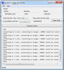


Any suggestion to solve this problem?

Parents
  • Hi,

    Have you powered the DK externally or through USB?

    Best regards,
    Jørgen

  • Hi Jorgen, I can power up the DK through J-link Plus using J-link Commander: "power on". I could enable Boot loader mode by pressing Boot/Reset button while power it up and the LED5 will blinking in slow pace.

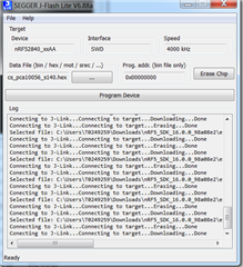
    By plugging USB cable from laptop to J2, I can manage to flash .hex file into the chip using J-Flash Lite.  

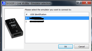
    The J-Flash can detect both onboard J-Link and external J-Link Plus connected to P18.

    However, when I used external J-link Plus to power up the board ( the board can be powered up) and then tried to flash .hex file into the chip, it showed me "Could not connect to target".

    So my doubt is whether the pin diagram of P18 (Debug in) for SWD interface (as posted above) is correct?

  • It may be that the external J-Link cannot supply enough power.  Did you try to switch the "nRF only switch" SW6 to disconnect the nRF52840 from the onboard debugger?  Otherwise you may still need to verify the power is sufficient?

  • Hi, I tried to switch SW6 to "nRF only" and LED5 turned off. Then I switched back SW6 to "Default" and power up the board from an external J-Link by "power on" command + pressing Boot/Reset button at the same time, LED5 can be turned on. So I think supply power is not the issue here?

  • LED5 indicates if the on-board Segger J-Link interface MCU is powered, it will not light up if SW6 is in the "nRF only" position, as the purpose of this switch is to disconnect interface MCU and additional components like LEDs, etc, to reduce the current consumption. Did you try flashing with switch in this position?

    Are you sure that the J-Link/J-Flash can provide suitable voltage for the nRF52840? From the interface description, it looks like pin 19 on the J-Link will output 5V, while pin 1 on P18 goes to the VDD_nRF domain, which is connected to the VDD input of the chip, not the high-voltage VDDH supply. You may redirect this pin to VDD, which will be regulated down to 3V by the on-board regulator, by cutting SB60 and solder SB59, see Debug input and trace for more details. However, note that you then may need to connect pin 1 of the J-Link interface (VTref) to VDD_nRF to get the correct voltage level for the interface. I think it will be easier to supply the DK externally than through the J-Link if it is not able to provide the appropriate voltage.

  • I was able to get this to work by doing the following:

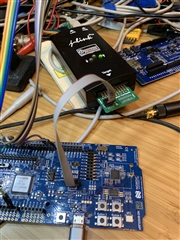
    1. I am using standard connector adapter for CortexM from JLink Pro as in photo connected to Debug In

    2. I plugged in USB cable at bottom connector 

    3. Switch to nRF Only

    4. Select USB Source on nRF Power Source

    5. Power Switch On.

    6. Access J-Link and comms seem to be working

Reply Children
Related