This post is older than 2 years and might not be relevant anymore
More Info: Consider searching for newer posts

Programming custom NRF52832 board using SWD interface

Hello NRF,

I have a custom board with NRF52832, and exposed the SWDIO, SWDCLK, GND, VDD, RESET pins for programming the board through the NRF52-DK board.

I started with a sample peripheral_uart, connected the NRF52-DK board to my PC, and managed to BUILD and RUN the sample application.

I verified that the app is working, by connecting to the UART service advertised by this app (on NRF52-DK) through another device that has NRF-TOOLBOX and used the UART service to query the NRF UART (NRF52-DK board) and managed to read write and verified the same over the console.

Now, I want to program my custom board, instead of the NRF52-DK board. Based on some suggestions on this site, I connected the

NRF52-DK        CUSTOM_BOARD

SWDIO             SWDIO

SWDCLK          SWDCLK

GND-DET         GND

VTG                 VDD/3V3

I then powered my board and then tried the BUILD and RUN option on the SEGGER.

It seems like my custom board is not getting programmed.

I would like to know : 

1. Do I have to first program a bootloader on to my custom board. If so, please advise a boot loader that I can download from your site (if possible) and the steps to program the same on to my custom board.

2. How to program the compiled/build binary/hex files on to my custom card? Just BUILD and RUN would download the binary on to the connected custom board, instead of the NRF52-DK board? (because my custom board is connected through the SWD port and GND detected?) If BUILD and RUN wouldn't work, where can I find the compiled binary or hex file where I can program the same on to the custom board , perhaps by using command line nrfjprog tool???

3. I believe the peripheral_uart has it's pin definitions, for the RX, TX, LEDs etc. Since my custom board pin assignments might be different from that of the NRF52-DK, where can I find these definitions, so I can go map the pins?

All I need is to demonstrate this peripheral_uart app on my custom nrf52832 board, where I will connect a serial port on to its RX/TX to a putty terminal (on my pc) and then able to rx/tx data back and forth with the other connected device (NRF toolbox -> UART).

I appreciate your help in this regard.

regards,

Dinesh.

Parents
  • Hi

    1. In the nRF5 SDK you can edit the following defines in the project's sdk_config.h header file to these values to enable the RC oscillator and calibration.

    // <h> Clock - SoftDevice clock configuration
    
    //==========================================================
    // <o> NRF_SDH_CLOCK_LF_SRC  - SoftDevice clock source.
     
    // <0=> NRF_CLOCK_LF_SRC_RC 
    // <1=> NRF_CLOCK_LF_SRC_XTAL 
    // <2=> NRF_CLOCK_LF_SRC_SYNTH 
    
    #ifndef NRF_SDH_CLOCK_LF_SRC
    #define NRF_SDH_CLOCK_LF_SRC 0
    #endif
    
    // <o> NRF_SDH_CLOCK_LF_RC_CTIV - SoftDevice calibration timer interval. 
    #ifndef NRF_SDH_CLOCK_LF_RC_CTIV
    #define NRF_SDH_CLOCK_LF_RC_CTIV 16
    #endif
    
    // <o> NRF_SDH_CLOCK_LF_RC_TEMP_CTIV - SoftDevice calibration timer interval under constant temperature. 
    // <i> How often (in number of calibration intervals) the RC oscillator shall be calibrated
    // <i>  if the temperature has not changed.
    
    #ifndef NRF_SDH_CLOCK_LF_RC_TEMP_CTIV
    #define NRF_SDH_CLOCK_LF_RC_TEMP_CTIV 2
    #endif
    
    // <o> NRF_SDH_CLOCK_LF_ACCURACY  - External clock accuracy used in the LL to compute timing.
     
    // <0=> NRF_CLOCK_LF_ACCURACY_250_PPM 
    // <1=> NRF_CLOCK_LF_ACCURACY_500_PPM 
    // <2=> NRF_CLOCK_LF_ACCURACY_150_PPM 
    // <3=> NRF_CLOCK_LF_ACCURACY_100_PPM 
    // <4=> NRF_CLOCK_LF_ACCURACY_75_PPM 
    // <5=> NRF_CLOCK_LF_ACCURACY_50_PPM 
    // <6=> NRF_CLOCK_LF_ACCURACY_30_PPM 
    // <7=> NRF_CLOCK_LF_ACCURACY_20_PPM 
    // <8=> NRF_CLOCK_LF_ACCURACY_10_PPM 
    // <9=> NRF_CLOCK_LF_ACCURACY_5_PPM 
    // <10=> NRF_CLOCK_LF_ACCURACY_2_PPM 
    // <11=> NRF_CLOCK_LF_ACCURACY_1_PPM 
    
    #ifndef NRF_SDH_CLOCK_LF_ACCURACY
    #define NRF_SDH_CLOCK_LF_ACCURACY 1
    #endif

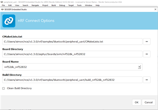
    2. In NCS, you need to go to the "Configure NCS project" option in the Project dropdown folder in SES and change the Clock control source to use the RC oscillator instead of external crystal.

    Please note that if you've followed the sparkfun schematics you should have this external crystal however, so this should not be the issue it seems. Are you able to run the example project on the nRF52 DK?

    Are you using the toolchain manager in nRFConnect to set up the nRFConnect SDK, or do you refer to the getting started guide? I would recommend using the toolchain manager for new users, as this is easier to get started with. When opening the SES IDE, how do you open the project. Please note that you should "Open nRFConnect SDK project" in "File" when opening new projects in NCS.

    Best regards,

    Simon

Reply
  • Hi

    1. In the nRF5 SDK you can edit the following defines in the project's sdk_config.h header file to these values to enable the RC oscillator and calibration.

    // <h> Clock - SoftDevice clock configuration
    
    //==========================================================
    // <o> NRF_SDH_CLOCK_LF_SRC  - SoftDevice clock source.
     
    // <0=> NRF_CLOCK_LF_SRC_RC 
    // <1=> NRF_CLOCK_LF_SRC_XTAL 
    // <2=> NRF_CLOCK_LF_SRC_SYNTH 
    
    #ifndef NRF_SDH_CLOCK_LF_SRC
    #define NRF_SDH_CLOCK_LF_SRC 0
    #endif
    
    // <o> NRF_SDH_CLOCK_LF_RC_CTIV - SoftDevice calibration timer interval. 
    #ifndef NRF_SDH_CLOCK_LF_RC_CTIV
    #define NRF_SDH_CLOCK_LF_RC_CTIV 16
    #endif
    
    // <o> NRF_SDH_CLOCK_LF_RC_TEMP_CTIV - SoftDevice calibration timer interval under constant temperature. 
    // <i> How often (in number of calibration intervals) the RC oscillator shall be calibrated
    // <i>  if the temperature has not changed.
    
    #ifndef NRF_SDH_CLOCK_LF_RC_TEMP_CTIV
    #define NRF_SDH_CLOCK_LF_RC_TEMP_CTIV 2
    #endif
    
    // <o> NRF_SDH_CLOCK_LF_ACCURACY  - External clock accuracy used in the LL to compute timing.
     
    // <0=> NRF_CLOCK_LF_ACCURACY_250_PPM 
    // <1=> NRF_CLOCK_LF_ACCURACY_500_PPM 
    // <2=> NRF_CLOCK_LF_ACCURACY_150_PPM 
    // <3=> NRF_CLOCK_LF_ACCURACY_100_PPM 
    // <4=> NRF_CLOCK_LF_ACCURACY_75_PPM 
    // <5=> NRF_CLOCK_LF_ACCURACY_50_PPM 
    // <6=> NRF_CLOCK_LF_ACCURACY_30_PPM 
    // <7=> NRF_CLOCK_LF_ACCURACY_20_PPM 
    // <8=> NRF_CLOCK_LF_ACCURACY_10_PPM 
    // <9=> NRF_CLOCK_LF_ACCURACY_5_PPM 
    // <10=> NRF_CLOCK_LF_ACCURACY_2_PPM 
    // <11=> NRF_CLOCK_LF_ACCURACY_1_PPM 
    
    #ifndef NRF_SDH_CLOCK_LF_ACCURACY
    #define NRF_SDH_CLOCK_LF_ACCURACY 1
    #endif

    2. In NCS, you need to go to the "Configure NCS project" option in the Project dropdown folder in SES and change the Clock control source to use the RC oscillator instead of external crystal.

    Please note that if you've followed the sparkfun schematics you should have this external crystal however, so this should not be the issue it seems. Are you able to run the example project on the nRF52 DK?

    Are you using the toolchain manager in nRFConnect to set up the nRFConnect SDK, or do you refer to the getting started guide? I would recommend using the toolchain manager for new users, as this is easier to get started with. When opening the SES IDE, how do you open the project. Please note that you should "Open nRFConnect SDK project" in "File" when opening new projects in NCS.

    Best regards,

    Simon

Children
No Data
Related