Hi There,
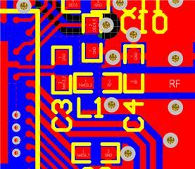
I am using NRF52840 chips in my system. Right now I am designing antenna for the chips. I think the reference SCH of nrf52840 have been completed the match from chip output to 50 ohm impendance transmission line by a matching network which include 2 pcs 1.0pf capcaitances and 1pcs 3.9nH inductance. Because I want simulation the antenna ,so I try to calculate the impedance of the micro-strip in PCA10056 and the impedance of the GCPW in PCA10059. The thing that puzzles me is that the impedance of these transmission lines is calculated not as 50ohm but as 100ohm.
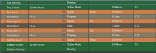
Below are the parameters entered into the microstrip impedance calculator in order to calculate the microstrip line impedance of the PCA10056.

Q1: Is there someone can tell me what is wrong I did. I notice the antenna connector J1 of PCA10056 is be required a 50 ohm impedance. I also calculate the transmission line impendance of PCA10059, It is 100ohm too.
Q2: What is the characteristic impedance of the nrf52840's RF output pin (I know we donot need it because the matching network have beeen proved by Nordic), I can try to verify my matching network way.
Q3, For calculate the transmission line impendance, how I can get the dielectric constant (Er) of a mult-layer PCB which Er of dielectric layer is difference.
Thanks,
B,Rs
Di-sheng