This post is older than 2 years and might not be relevant anymore
More Info: Consider searching for newer posts

Nrf52840 Antenn matching and micro-strip characteristic impedance

Hi There,

I am using NRF52840 chips in my system. Right now I am designing antenna for the chips. I think the reference SCH of nrf52840 have been completed the match from chip output to 50 ohm impendance transmission line by a matching network which include 2 pcs 1.0pf capcaitances and 1pcs 3.9nH inductance. Because I want simulation the antenna ,so I try to calculate the impedance of the micro-strip in PCA10056 and  the impedance of the GCPW in PCA10059. The thing that puzzles me is that the impedance of these transmission lines is calculated not as 50ohm but as 100ohm.

Below are the parameters entered into the microstrip impedance calculator in order to calculate the microstrip line impedance of the PCA10056.
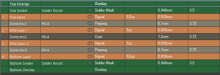
Q1:  Is there someone can tell me what is wrong I did. I notice the antenna connector J1 of PCA10056 is be required a 50 ohm impedance.  I also calculate the transmission line impendance of  PCA10059, It is 100ohm too.

Q2:  What is the characteristic impedance of the nrf52840's RF output pin (I know we donot need it because the matching network have beeen proved by Nordic), I can try to verify my  matching network way.

Q3, For calculate the transmission line impendance, how I can get the dielectric constant (Er) of a mult-layer PCB which   Er of dielectric layer  is difference.

Thanks,

B,Rs

Di-sheng


Parents
  • Correction: There is a error in the above 

    The PCA10059's RF transmission line impendance is 29.43713ohm  by GCPW calculation method.

    Thanks,

    Di-sheng

  • 1. Note that the transmission lines used on DKs are co-planar waveguides and somewhat different from striplines. Download a copy of Appcad and check the calculations there. 

    The difference between a microstrip line and a co-planar waveguide is that the latter also takes the same side ground plane into the calculations. 

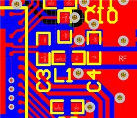
    2. As you say, the impedance isn't really needed as the matching network will take care of that for you. Note that the matching network also does harmonic filtering, so it's important to get the layout correct. Note how C3 is grounded here: 

    Check the component values in the reference schematic at https://infocenter.nordicsemi.com/topic/ps_nrf52840/ref_circuitry.html#concept_hqh_j22_fq. Looks like you have a very old version of the schematic as the values are different from what you say. 

    3. This depends slightly on the substrate, but Er for FR4 is usually about 4.6

  • Hi Ketiljo

    Thanks for your reply.

    I recalculated the 50ohm feeders for PCA10056 and PCA10059 using three tools (APPCAD, ADS and Feeder calculator on the Internet) according to the grounded coplanar waveguide. The impedance  of PCA10056 is about 64.5ohm and PCA10059 is about 46.5ohm

    My question:

    Q1: Why are they not designed to be accurate 50ohm impedance?

    Q2: For the reference V1.1PCB, its layer stack is FR4Core (Er=4.8)+Prepreg(Er=4.2)+ Core (Er=4.2).

    Are there any benefits to choosing such a PCB layer stack?

    Q3: For the V1.1 reference PCB, the nRF52840 chip side matching network (C3= 0.8pf;L1 = 4.7 uH.Does C4=0.5PpF) match to the exact 50ohm or something?

    Q4: Since the V1.1 reference PCB is separated by media with different relative dielectric constants, I have no way to use tool software to calculate the size of the 50ohm feeder. Can you tell me how to calculate the feeder impedance of such mixed media?

    Q5: For the V1.1 reference PCB, if the chip side matching network matches the output impedance of the chip to the exact 50ohm, then if I change the PCB layer stack, as long as I change the feeder to the exact 50ohm feeder, there will be no impact on the RF transmission, right?

    Because my PCB manufacturer prefers the prepreg+core+prepreg layer stack.

    Q6: If possible, could you please tell me the output impedance of the RF pin of the nRF52840 chip, so that I can check my RF design through simulation


    Thanks

    B.Rs

    Di-sheng

Reply
  • Hi Ketiljo

    Thanks for your reply.

    I recalculated the 50ohm feeders for PCA10056 and PCA10059 using three tools (APPCAD, ADS and Feeder calculator on the Internet) according to the grounded coplanar waveguide. The impedance  of PCA10056 is about 64.5ohm and PCA10059 is about 46.5ohm

    My question:

    Q1: Why are they not designed to be accurate 50ohm impedance?

    Q2: For the reference V1.1PCB, its layer stack is FR4Core (Er=4.8)+Prepreg(Er=4.2)+ Core (Er=4.2).

    Are there any benefits to choosing such a PCB layer stack?

    Q3: For the V1.1 reference PCB, the nRF52840 chip side matching network (C3= 0.8pf;L1 = 4.7 uH.Does C4=0.5PpF) match to the exact 50ohm or something?

    Q4: Since the V1.1 reference PCB is separated by media with different relative dielectric constants, I have no way to use tool software to calculate the size of the 50ohm feeder. Can you tell me how to calculate the feeder impedance of such mixed media?

    Q5: For the V1.1 reference PCB, if the chip side matching network matches the output impedance of the chip to the exact 50ohm, then if I change the PCB layer stack, as long as I change the feeder to the exact 50ohm feeder, there will be no impact on the RF transmission, right?

    Because my PCB manufacturer prefers the prepreg+core+prepreg layer stack.

    Q6: If possible, could you please tell me the output impedance of the RF pin of the nRF52840 chip, so that I can check my RF design through simulation


    Thanks

    B.Rs

    Di-sheng

Children
  • 1. Achieving exactly 50 ohm isn't trivial, but close to 50 ohm is good enough. Even if you have a 75 ohm transmission line in a 50 ohm system, the loss is only 0.2 dB due to mismatch. The loss in the trace comes on top of this. So unless you have a very long line, this is fine. 

    2. Whatever you can get is ok.

    3. Close, but if you measure it, you will find that the impedance measured into the matching network with the TX in 8 dBm mode is closer to 70-80 ohm as this gives less harmonics. 

    4. That depends where you place the ground plane. But again, this isn't very critical. Use the Er value for the thickest part. 

    5. Basically, yes. 

    6. The output impedance of a PA is less important. You like to know what impedance the PA will like to see to perform well: 35 - j 35 ohm

Related