
Hi,
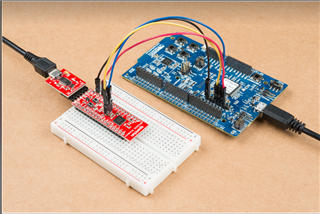
I am trying to test the uart exemple on nrf52840 using external debugging as shown in figure but it doesn't function !!!!
are there any modifications that need to be added compared to the internal debugging mode or is it the same thing?
Hi,
I am trying to test the uart exemple on nrf52840 using external debugging as shown in figure but it doesn't function !!!!
are there any modifications that need to be added compared to the internal debugging mode or is it the same thing?
Hi,
What board are you're flashing the UART example on?
are there any modifications that need to be added compared to the internal debugging mode or is it the same thing?
Yes, you need to change the board map file so that the pins on fits the board that you're using.
regards
Jared
I am flashing the example on the board nrf52832 and I put the connection of pins as following
Rx==> P08 (Pins of nrf52840)
Tx==>P06
CTS==>P07
RTS==>P05
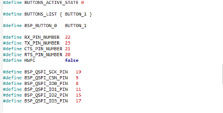
then I put modification on the file pca10040.h to get the correspendant pin of nrf52840 but it doesn't function .
Hi,
If I understand you correctly.: You are flashing the red board which has a nRF52840 with the UART example from the SDK. You also flash the a nRF52 DK with the example, and try to connect the two. Is my understanding correct?
The image that you shared shows that you have connected the nRF52840 based board to the P20 header on the nRF52 DK. The P20 header can not be used for UART, they are used to debug an external board.
Pin 23, 22, 20 is located on the header over P20.
regards
Jared
yes I have already modified the pins as follows
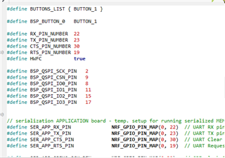 and it works in the segger terminal using RTT but the serial communication does not take place, that is to say when I try to test with putty it does not work
Si je vous comprends bien: vous faites clignoter le tableau rouge qui a un nRF52840 avec l'exemple UART du SDK. Vous flashez également le nRF52 DK avec l'exemple et essayez de connecter les deux. Ma compréhension est-elle correcte?
Yes I need to test the UART example with external debug that means on the red board
Hi.
nikola said:Yes I need to test the UART example with external debug that means on the red board
Ok. I'm still a bit confused over what the image was supposed to show.
nikola said:and it works in the segger terminal using RTT but the serial communication does not take place, that is to say when I try to test with putty it does not work
Seems that you're referring to the log outputs. How is the logger configured in your sdk_config.h file? Can you upload your config file?
regards
Jared
Hi,
Could you try to disable the RTT backend and see if the log output is displayed on PuTTY. Set
I disable the RTT backend but it doesn't work in putty
Hi,
So I'm not sure how I was able to miss this but using UART as a backend for the logger and at the same time using it in the application is not possible. You would therefore have to use RTT as the backend. I'm very sorry that I didn't realize this before.
regards
Jared

