I designed a prototype custom board with the nrf52840 (QIAAD0).
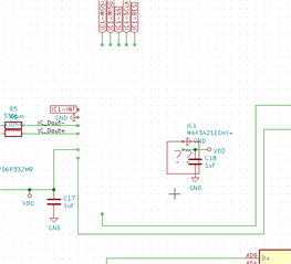
It has a USB socket, with an external LDO supplying 3.3V to VDDH + VDD (following the recommended circuit configuration from the manual under "Figure 212: Circuit configuration no. 3 schematic").
I can flash and debug it with a J-Link debugger, the USB interface however seems to be nonfunctional.
The debugger shows a value of 0 at 0x40000438 (USBREGSTATUS), which I interpret as VBUS detection not working.
I measured the following (at vias close to the MCU):
- 3.25V at VDD and VDDH
- 5V at VBUS
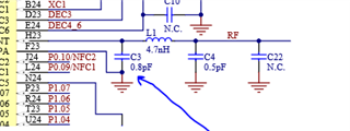
- 0V at D+/D-
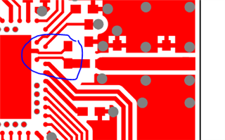
I guess this is somehow a fault of my board design, but I'm a bit at a loss how to debug this further. Any advice would be appreciated.