I am using the SAADC example to check the sampling rate between ADC and UART.
I am using an Arduino serial plotter and logic analyzer to check the correct data.
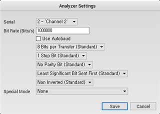
To check this, the following settings were made.
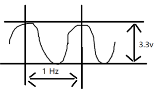
1 Hz, 3.3 Vp-p
0.nRF52832
Baud rate 1000000
ADC Sampling bit 12bit
Modify the source code to check the optimized Arduino float output value (data [4byte] + newline character [2byte] = 6byte)
Source code
/**
 * Copyright (c) 2014 - 2019, Nordic Semiconductor ASA
 *
 * All rights reserved.
 *
 * Redistribution and use in source and binary forms, with or without modification,
 * are permitted provided that the following conditions are met:
 *
 * 1. Redistributions of source code must retain the above copyright notice, this
 *    list of conditions and the following disclaimer.
 *
 * 2. Redistributions in binary form, except as embedded into a Nordic
 *    Semiconductor ASA integrated circuit in a product or a software update for
 *    such product, must reproduce the above copyright notice, this list of
 *    conditions and the following disclaimer in the documentation and/or other
 *    materials provided with the distribution.
 *
 * 3. Neither the name of Nordic Semiconductor ASA nor the names of its
 *    contributors may be used to endorse or promote products derived from this
 *    software without specific prior written permission.
 *
 * 4. This software, with or without modification, must only be used with a
 *    Nordic Semiconductor ASA integrated circuit.
 *
 * 5. Any software provided in binary form under this license must not be reverse
 *    engineered, decompiled, modified and/or disassembled.
 *
 * THIS SOFTWARE IS PROVIDED BY NORDIC SEMICONDUCTOR ASA "AS IS" AND ANY EXPRESS
 * OR IMPLIED WARRANTIES, INCLUDING, BUT NOT LIMITED TO, THE IMPLIED WARRANTIES
 * OF MERCHANTABILITY, NONINFRINGEMENT, AND FITNESS FOR A PARTICULAR PURPOSE ARE
 * DISCLAIMED. IN NO EVENT SHALL NORDIC SEMICONDUCTOR ASA OR CONTRIBUTORS BE
 * LIABLE FOR ANY DIRECT, INDIRECT, INCIDENTAL, SPECIAL, EXEMPLARY, OR
 * CONSEQUENTIAL DAMAGES (INCLUDING, BUT NOT LIMITED TO, PROCUREMENT OF SUBSTITUTE
 * GOODS OR SERVICES; LOSS OF USE, DATA, OR PROFITS; OR BUSINESS INTERRUPTION)
 * HOWEVER CAUSED AND ON ANY THEORY OF LIABILITY, WHETHER IN CONTRACT, STRICT
 * LIABILITY, OR TORT (INCLUDING NEGLIGENCE OR OTHERWISE) ARISING IN ANY WAY OUT
 * OF THE USE OF THIS SOFTWARE, EVEN IF ADVISED OF THE POSSIBILITY OF SUCH DAMAGE.
 *
 */
/** @file
 * @defgroup nrf_adc_example main.c
 * @{
 * @ingroup nrf_adc_example
 * @brief ADC Example Application main file.
 *
 * This file contains the source code for a sample application using ADC.
 *
 * @image html example_board_setup_a.jpg "Use board setup A for this example."
 */

#include <stdbool.h>
#include <stdint.h>
#include <stdio.h>
#include <string.h>
#include "nrf.h"
#include "nrf_drv_saadc.h"
#include "nrf_drv_ppi.h"
#include "nrf_drv_timer.h"
#include "boards.h"
#include "app_error.h"
#include "nrf_delay.h"
#include "app_util_platform.h"
#include "nrf_pwr_mgmt.h"

#include "nrf_log.h"
#include "nrf_log_ctrl.h"
#include "nrf_log_default_backends.h"

#define SAMPLES_IN_BUFFER 1
volatile uint8_t state = 1;

static const nrf_drv_timer_t m_timer = NRF_DRV_TIMER_INSTANCE(0);
static nrf_saadc_value_t     m_buffer_pool[2][SAMPLES_IN_BUFFER];
static nrf_ppi_channel_t     m_ppi_channel;
static uint32_t              m_adc_evt_counter;


void timer_handler(nrf_timer_event_t event_type, void * p_context)
{

}


void saadc_sampling_event_init(void)
{
    ret_code_t err_code;

    err_code = nrf_drv_ppi_init();
    APP_ERROR_CHECK(err_code);

    nrf_drv_timer_config_t timer_cfg = NRF_DRV_TIMER_DEFAULT_CONFIG;
    timer_cfg.bit_width = NRF_TIMER_BIT_WIDTH_32;
    err_code = nrf_drv_timer_init(&m_timer, &timer_cfg, timer_handler);
    APP_ERROR_CHECK(err_code);

    /* setup m_timer for compare event every 400ms */
    uint32_t ticks = nrf_drv_timer_us_to_ticks(&m_timer, 110);
    nrf_drv_timer_extended_compare(&m_timer,
                                   NRF_TIMER_CC_CHANNEL0,
                                   ticks,
                                   NRF_TIMER_SHORT_COMPARE0_CLEAR_MASK,
                                   false);
    nrf_drv_timer_enable(&m_timer);

    uint32_t timer_compare_event_addr = nrf_drv_timer_compare_event_address_get(&m_timer,
                                                                                NRF_TIMER_CC_CHANNEL0);
    uint32_t saadc_sample_task_addr   = nrf_drv_saadc_sample_task_get();

    /* setup ppi channel so that timer compare event is triggering sample task in SAADC */
    err_code = nrf_drv_ppi_channel_alloc(&m_ppi_channel);
    APP_ERROR_CHECK(err_code);

    err_code = nrf_drv_ppi_channel_assign(m_ppi_channel,
                                          timer_compare_event_addr,
                                          saadc_sample_task_addr);
    APP_ERROR_CHECK(err_code);
}


void saadc_sampling_event_enable(void)
{
    ret_code_t err_code = nrf_drv_ppi_channel_enable(m_ppi_channel);

    APP_ERROR_CHECK(err_code);
}


void saadc_callback(nrf_drv_saadc_evt_t const * p_event)
{
    if (p_event->type == NRF_DRV_SAADC_EVT_DONE)
    {
        ret_code_t err_code;

        err_code = nrf_drv_saadc_buffer_convert(p_event->data.done.p_buffer, SAMPLES_IN_BUFFER);
        APP_ERROR_CHECK(err_code);

        int i;
        //NRF_LOG_INFO("ADC event number: %d", (int)m_adc_evt_counter);

        for (i = 0; i < SAMPLES_IN_BUFFER; i++)
        {
            NRF_LOG_RAW_INFO("%d\n", p_event->data.done.p_buffer[i]);
        }
        m_adc_evt_counter++;
    }
}


void saadc_init(void)
{
    ret_code_t err_code;
    nrf_saadc_channel_config_t channel_config =
        NRF_DRV_SAADC_DEFAULT_CHANNEL_CONFIG_SE(NRF_SAADC_INPUT_AIN0);

    err_code = nrf_drv_saadc_init(NULL, saadc_callback);
    APP_ERROR_CHECK(err_code);

    err_code = nrf_drv_saadc_channel_init(0, &channel_config);
    APP_ERROR_CHECK(err_code);

    err_code = nrf_drv_saadc_buffer_convert(m_buffer_pool[0], SAMPLES_IN_BUFFER);
    APP_ERROR_CHECK(err_code);

    err_code = nrf_drv_saadc_buffer_convert(m_buffer_pool[1], SAMPLES_IN_BUFFER);
    APP_ERROR_CHECK(err_code);

}


/**
 * @brief Function for main application entry.
 */
int main(void)
{
    uint32_t err_code = NRF_LOG_INIT(NULL);
    APP_ERROR_CHECK(err_code);

    NRF_LOG_DEFAULT_BACKENDS_INIT();

    ret_code_t ret_code = nrf_pwr_mgmt_init();
    APP_ERROR_CHECK(ret_code);

    saadc_init();
    saadc_sampling_event_init();
    saadc_sampling_event_enable();
    NRF_LOG_INFO("SAADC HAL simple example started.");

    while (1)
    {
        nrf_pwr_mgmt_run();
        NRF_LOG_FLUSH();
    }
}


/** @} */
1. Logic Analyzer
2. Arduino serial plotter
Baud rate 1000000
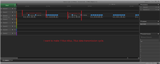
I have confirmed that data is transmitted well in the sampling cycle of 110us, but it fails in communication at 70us.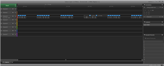
Data transmitted normally [sampling cycle 110us]
I want to change the sampling from 110 to 70. (Increase data sampling)
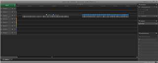
Dropped log out (sampling cycle 70us)
In theory, it turns out a speed of about 20k. (Ignore start/stop bits)
The calculation formula is as follows: 1000000 [Baud rate] / 8[data bit] / 6[char count] = 20,833
I used the following formula to check the number of samples.
Data transmission period (ms) = [sampling time] * [buffer count]
Number of interrupts per second = 1 / [Data transmission period (ms)] * 1000
ADC sampling count = [Number of interrupts per second] * [buffer count]