This post is older than 2 years and might not be relevant anymore
More Info: Consider searching for newer posts

Configure second UART on nRF9160 DK

I've been trying to configure a second UART for use on the nRF9160 DK.  However, I'm having some issues getting anything to send over the UART.  I feel like I'm missing something simple.  I configured and setup UART0 to PO.10, 11, 12, and 13 on the DK.  I then setup UART1 to PO.14, 15, 16, and 20.  I am able to send strings and print them out to UART0 (along with all the normal boot up messages and prink status messages that's default to UART0).  But I can't seem to get anything to on UART1.  

For my test setup I have two serial to FTDI USB converters that are connected to a terminal program so I can watch for any outputs.  I have modified both the overlay files for the SPM in the sample folder and also for my custom code.  I've also checked the .dts files after I've compiled in the build folder and it looks to be configured correctly.  So I'm not sure why I am unable to actually send something.

I started with the UART code example from Github and modified from there.  Running my code below results in UART0 outputting correctly but nothing being output on UART1.  My ultimate goal is to read character stings that I'll be sending to UART1 via my terminal program.  If I try to send anything to UART1, it appears to be ignored and I see no calls to the uart_cb1() function I have.  However, it is working for UART0.  If send a message from my terminal program to the nRF9160, I see uart_cb0() called and the data is repeated back to me over UART0.

I started with the uart example on Github here: https://github.com/Rallare/fw-nrfconnect-nrf/blob/nrf9160_samples/samples/nrf9160/uart/src/main.c#L31

And I've gone through some of the devzone tickets: 

https://devzone.nordicsemi.com/f/nordic-q-a/44648/how-to-communicate-an-external-module-through-uart-in-nrf9160dk

https://devzone.nordicsemi.com/f/nordic-q-a/44470/nrf9160-dk-gpio-uart

.DTS file
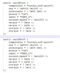
overlay file
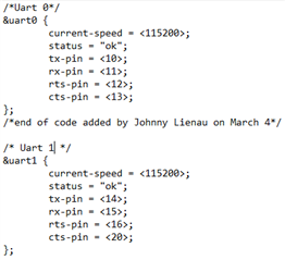
My Code:

#include <zephyr.h>
#include <misc/printk.h>
#include <uart.h>
#include <string.h>
#include <stdlib.h>

static u8_t uart_buf[1024];
static char *command0 = "This Is A Test of UART0\r\n";
static char *command1 = "This Is A Test of UART1\r\n";
u8_t i = 0;

void uart_cb0(struct device *x)
{
	uart_irq_update(x); //start processing interrupts in the ISR
	int data_length = 0;

	if (uart_irq_rx_ready(x)) { //check if UART RX buffer has a received char
		data_length = uart_fifo_read(x, uart_buf, sizeof(uart_buf)); //read ata from FIFO
		uart_buf[data_length] = 0;
	}
	printk("%s", uart_buf);
}

void uart_cb1(struct device *x)
{
	uart_irq_update(x);
	int data_length = 0;

	if (uart_irq_rx_ready(x)) {
		data_length = uart_fifo_read(x, uart_buf, sizeof(uart_buf));
		uart_buf[data_length] = 0;
	}
	printk("%s", uart_buf);
}


void uart_send_str(struct device *uart, char *str){
    printk("callback!\r\n");
    u32_t len = strlen(str);
    while (len--) {
        uart_poll_out(uart, *str++);
    }
}

void main(void)
{
        printk("Hello World\n");

	struct device *uart0 = device_get_binding("UART_0");
	uart_irq_callback_set(uart0, uart_cb0);
	uart_irq_rx_enable(uart0);
        printk("uart0 ready\n");

	struct device *uart1 = device_get_binding("UART_1");
	uart_irq_callback_set(uart1, uart_cb1);
	uart_irq_rx_enable(uart1);
        printk("uart1 ready\n");

	printk("UART loopback start!\n");
	while (1) {               
                uart_send_str(uart0, command0);
                uart_send_str(uart1, command1);
		k_cpu_idle();
	}
}

  • Forgot my config file:

    CONFIG_SERIAL=y
    CONFIG_TRUSTED_EXECUTION_NONSECURE=y
    CONFIG_UART_INTERRUPT_DRIVEN=y
    CONFIG_MAIN_STACK_SIZE=4096
    CONFIG_UART_0_NRF_UARTE=y
    CONFIG_UART_1_NRF_UARTE=y
    

  • Hello, 

    Can you please try to add the following to your config file:

    CONFIG_BOARD_PCA10090_UART1_ARDUINO=y


    Ref. this guide from my colleague:
    https://devzone.nordicsemi.com/f/nordic-q-a/45476/connecting-uart1-to-a-periph-on-nrf9160-dk/178988#178988

    Let me know if that helps. 

    Kind regards,
    Øyvind

  • Hello, thanks for the reply.  Adding that line still does not seem to make it work. 

    Reading the post you linked, it seems that they were using I/O pins that were not originally routed to headers on the DK.  The ones I've chosen (P0.14, 15, 16, 20)  should all be default routed to the header pins.  I shouldn't need to reprogram or change the nRF52 or adjust the virtual com port settings because of that.  Is that correct?

  • Yes, I'm sorry, but I had to try as I did not see anything out of the ordinary in your setup.

    One of the answers, where UART2 is used for modem tracing, threw me off a little. This is actually UART1

    #ifdef CONFIG_BSD_LIBRARY_TRACE_ENABLED
    /* Use UARTE1 as a dedicated peripheral to print traces. */
    static const nrfx_uarte_t uarte_inst = NRFX_UARTE_INSTANCE(1);
    #endif


    Can you please try to add the following to your config file:
    CONFIG_BSD_LIBRARY_TRACE_ENABLED=n


    jlienau03 said:
    I shouldn't need to reprogram or change the nRF52 or adjust the virtual com port settings because of that.  Is that correct?

     Did you try with default pin configuration as stated in the Board Controller chapter and VCOM chapter? Have you ensured that you are connected correctly with the FTDI?

    I am working on finding the correct answer my self, as the pin configuration is not very clear in the documentation.

  • Adding the CONFIG_BSD_LIBRARY_TRACE_ENABLED=n also did not work.  But since I'm using the uart example from github, I don't believe it uses the BSD library anyway.

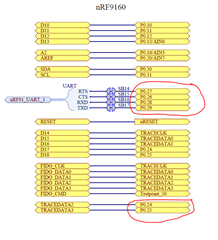
    I did notice that there are two additional unused I/Os on the DK.  P0.24 and P0.25 look like they go to pin headers on the DK and are not default routed through anything else.  If I do not use RTS/CTS I can configure UART1 to use TX and RX pins only on P0.24 and P0.25.  I was able to get it successfully working like that and had two way communication with my terminal program.

    Alternatively, it looks like P0.26, P0.27, P0.28, P0.29 can be routed away from the virtual com port by the nRF91_UART_CTRL line.  It's controlled by the nRF52 has to be driven high.  Rather than reprogram the nRF52 I just drove that line high by jumping R69 to 3V Slight smile  This way I didn't have to mess with programming it.  However, I then discovered that only P0.26, P0.27, and P0.28 route to headers on the DK.  I couldn't find P0.29 anywhere on the DK!  So long story short I used P0.25 and substituted that in for P0.29 since I knew that was available.

    Here's what my overlay and proj.conf files look like now.

    /*Uart 0*/
    &uart0 {
    	current-speed = <115200>;
    	status = "ok";
    	tx-pin = <10>;
    	rx-pin = <11>;
    	rts-pin = <12>;
    	cts-pin = <13>;
    };
    /*end of code added by Johnny Lienau on March 4*/
    
    /* Uart 1 */
    &uart1 {
    	current-speed = <115200>;
    	status = "ok";
    	tx-pin = <25>; 
    	rx-pin = <26>; 
    	rts-pin = <27>;
    	cts-pin = <28>;
    };

    CONFIG_SERIAL=y
    
    CONFIG_TRUSTED_EXECUTION_NONSECURE=y
    
    CONFIG_UART_INTERRUPT_DRIVEN=y
    
    CONFIG_MAIN_STACK_SIZE=4096
    CONFIG_UART_0_NRF_UARTE=y
    CONFIG_UART_1_NRF_UARTE=y
    

    I think it would be REALLY nice if on the next revision of the DK, you guys put a physical switch so users could manually route P026, 27, 28, and 29 to the headers.  I'm sure I'm not the only person looking to route two com ports to the headers.

Related