This post is older than 2 years and might not be relevant anymore
More Info: Consider searching for newer posts

Erase the preload code for the external board

I have two BC805M EK

Board 1: when I upload the (LED controlled by reset button) code to it, it works fine. 

Board 2: when I upload the LED control code to it, I could see the code has been uploaded correctly by observing the LED (flash twice). However,  whenever I press the reset button, the board restarts the code from beginning again (i.e. LED flashes twice again). 

The code is given below: 

int main(void)
{    
    // Read <nrf_gpio.h> for more details of the following macros
    nrf_gpio_cfg_output(RED_LED_PIN);                             // Configure the pin as the output
    nrf_gpio_cfg_input(BUTTON_PIN,GPIO_PIN_CNF_PULL_Disabled);    // Configure the pin as the input
    
    // Toohle Red LED on and off
    
    nrf_gpio_pin_clear(RED_LED_PIN);    // Set the pin to LOW
    nrf_delay_ms(100);
    nrf_gpio_pin_set(RED_LED_PIN);      // Set the pin to HIGH
    nrf_delay_ms(100);
    nrf_gpio_pin_clear(RED_LED_PIN);
    nrf_delay_ms(100);
    nrf_gpio_pin_set(RED_LED_PIN);
    nrf_delay_ms(100);
    nrf_gpio_pin_clear(RED_LED_PIN);

    for(;;){
        // Read the BC805M EK schematic sheet to understand the logic
        RESET_BUTTON_STATE = nrf_gpio_pin_read(BUTTON_PIN);
        if (RESET_BUTTON_STATE==0)
        {
            nrf_gpio_pin_clear(RED_LED_PIN);  // If the Button pin voltage is LOW (pressed), set LED pin to LOW, hence, turn LED on
        }else{
            nrf_gpio_pin_set(RED_LED_PIN);    // If the Button pin voltage is HIGH (not pressed), set LED pin to LOW, hence, turn LED off
        } 
    }

}

2 boards have the same code, same hardware.

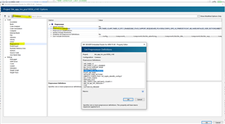
I don't know what I did to board 1 before. I guess it's caused by not easing the preload code on board #2? So I used nRF Connect on Windows PC ---> Programmer ---> Erase all, then re-upload the code, but it doesn't help. 

Do you have any other clue to this situation, please? Thanks! 

Parents Reply Children
  • Hi Vidar, thanks for your reply. 

    Today, when I tried to upload the same code to the BC805M board, they behave the same now. Maybe it was caused by the hardware connection issue yesterday. I mean, I tried to program both BC805M boards at the same time by using nRF52 DK. But they didn't share the GND and 3V3 pin, so I guess only 1 board was programmed yesterday. That's why 2 boards behave differently with the same code yesterday. 

    --------------------------------------------------------------------

    My new full code is here:

    #include <math.h>
    #include <stdbool.h>
    #include <stdio.h>
    #include <stdint.h>
    #include <string.h>
    
    #include "boards.h"
    #include "app_util_platform.h"
    #include "app_error.h"
    #include "nrf_delay.h"
    #include "nrf_gpio.h"
    #include "nordic_common.h"
    #include "nrf.h"
    #include "app_util_platform.h"
    #include "bsp_btn_ble.h"
    #include "nrf_log.h"
    #include "nrf_log_ctrl.h"
    #include "nrf_log_default_backends.h"
    
    
    #define  RED_LED_PIN   20
    #define  BUTTON_PIN    21
    int RESET_BUTTON_STATE;
    
    
    int main(void)
    {    
        
        // Read <nrf_gpio.h> for more details of the following macros
        nrf_gpio_cfg_output(RED_LED_PIN);                             // Configure the pin as the output
        nrf_gpio_cfg_input(BUTTON_PIN,GPIO_PIN_CNF_PULL_Pullup);    // Configure the pin as the input
    
        // Flash Red LED twice
        nrf_gpio_pin_clear(RED_LED_PIN);    // Set the pin to LOW
        nrf_delay_ms(100);
        nrf_gpio_pin_set(RED_LED_PIN);      // Set the pin to HIGH
        nrf_delay_ms(100);
        nrf_gpio_pin_clear(RED_LED_PIN);
        nrf_delay_ms(100);
        nrf_gpio_pin_set(RED_LED_PIN);
        nrf_delay_ms(100);
        
        while(true){
            // Read the BC805M EK schematic sheet to understand the logic
            RESET_BUTTON_STATE = nrf_gpio_pin_read(BUTTON_PIN);
            if (RESET_BUTTON_STATE==1)
            {
                nrf_gpio_pin_clear(RED_LED_PIN);  // If the Button pin voltage is LOW (pressed), set LED pin to LOW, hence, turn LED on
            }else{
                nrf_gpio_pin_set(RED_LED_PIN);    // If the Button pin voltage is HIGH (not pressed), set LED pin to LOW, hence, turn LED off
            } 
        }
    
    }


    Now the board behaves like: 

    When the code is uploaded successfully, the red LED flashes twice. Then LED stays ON. 

    If I press and hold the reset button (do not release), the red LED turns OFF. 

    However, as long as I release the reset button, the red LED flashes twice. So it seems like the board restarts. 

    My questions are:

    1) Why the board restarts when I release the reset button? I have already erased the preload code by using nRF Connect->Programmer->erase all. My code doesn't have any restarting function. 

    2) nrf_gpio_pin_read() function says: return 0 if the pin input level is low. Positive value if the pin is high. Does that mean this function returns 0 and 1 (true and false) ? If not, what's the range of positive value? 

    Thanks

  • 1) What's the pin number assigned to 'BUTTON_PIN'? You can't use P0.21 as a GPIO pin if it has the pinreset functionality enabled

    2) Yes, it can either be 1 or 0

  • #define  BUTTON_PIN    21

    The button pin is P0.21, this is a reset pin on the evaluation board. I'm using the evaluation board now. However, in my code, I didn't define P0.21 to be the reset function. 

    So why when I pressed the button, the board is reset (restarted), please? If this is the preload code/setting, could I erase this function, please? 

    thanks 

  • The 'CONFIG_GPIO_AS_PINRESET' flag is included in our SDK examples by default and this makes the startup file (system_nrf52805.c) enable pinreset.

    from system_nrf52805.c

        /* Configure GPIO pads as pPin Reset pin if Pin Reset capabilities desired. If CONFIG_GPIO_AS_PINRESET is not
          defined, pin reset will not be available. One GPIO (see Product Specification to see which one) will then be
          reserved for PinReset and not available as normal GPIO. */
        #if defined (CONFIG_GPIO_AS_PINRESET)
    
            #define RESET_PIN 21
    
            if (((NRF_UICR->PSELRESET[0] & UICR_PSELRESET_CONNECT_Msk) != (UICR_PSELRESET_CONNECT_Connected << UICR_PSELRESET_CONNECT_Pos)) ||
                ((NRF_UICR->PSELRESET[1] & UICR_PSELRESET_CONNECT_Msk) != (UICR_PSELRESET_CONNECT_Connected << UICR_PSELRESET_CONNECT_Pos))){
                NRF_NVMC->CONFIG = NVMC_CONFIG_WEN_Wen << NVMC_CONFIG_WEN_Pos;
                while (NRF_NVMC->READY == NVMC_READY_READY_Busy){}
                NRF_UICR->PSELRESET[0] = RESET_PIN;
                while (NRF_NVMC->READY == NVMC_READY_READY_Busy){}
                NRF_UICR->PSELRESET[1] = RESET_PIN;
                while (NRF_NVMC->READY == NVMC_READY_READY_Busy){}
                NRF_NVMC->CONFIG = NVMC_CONFIG_WEN_Ren << NVMC_CONFIG_WEN_Pos;
                while (NRF_NVMC->READY == NVMC_READY_READY_Busy){}
                NVIC_SystemReset();
            }
        #endif

  • Hi, thanks for your help. 

    In screenshot 1, I deleted CONFIG_GPIO_AS_PINRESET. 

    In system_nrf52805.c, I deleted all codes which you provided above. 

    However, the pin reset function on P0.21 still exists. Do you have any clue, please? Thanks in advance! 

Related