Dear Nordic support,
i'm evaluating the Nordic nRF52840_Dongle with the SDK 1.5.1, inlucing Zephyr etc. I could successfully compile and load the Blinky-example (..\ncs\v1.5.1\zephyr\samples\basic\blinky\build_nrf52840dongle_nrf52840) and manipulated it.
Now i am really struggeling to add a UART (a real UART, no CDC-USB) connection to the dongle. I promise i've read so many documentation (Zephyr, K-Config, Device-Tree, Nordic-SDK...). But i can't find answers...
---
1.) On which pins at the dongle, can i map the UART RX and TX pins?! Normally on a microcontroller i have a bunch of options, in the Nordic docs it looks like i can map them anywhere, can I? Precisely this configuration is feasible
zephyr.dts --
...
uart0: uart@40002000 {
reg = < 0x40002000 0x1000 >;
interrupts = < 0x2 0x1 >;
status = "okay";
label = "UART_0";
compatible = "nordic,nrf-uarte";
current-speed = < 0x1c200 >;
tx-pin = < 0x1f >;
rx-pin = < 0x1d >;
rts-pin = < 0x00 >;
cts-pin = < 0x00 >;
...
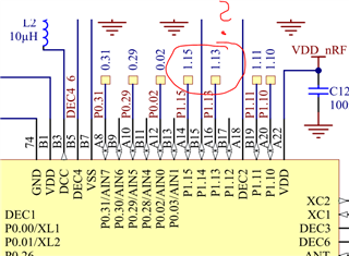
2.) In the docs and even in the video the pins are numbered like "30", "31" and so on. But the in ref-maunal and the schematic there ist port number AND the pin number , e.g 0.12, 1.15, how do i address 1.15, when i want to used it as a UART pin in the config overlay file?
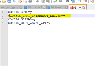
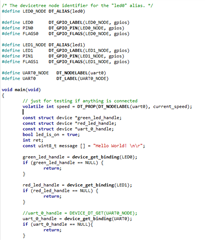
3.) In the picture below, there is my code of the blinky example, including my attemps of using the UART via the zephyr-API. The Problem is, that the "device_get_binding" - function returns a NULL-pointer. I have no idea why.
Thanks a lot.
Sören