This post is older than 2 years and might not be relevant anymore
More Info: Consider searching for newer posts

ISP with nRF6700 and radio module with nrf24le1

Hi there,

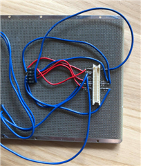
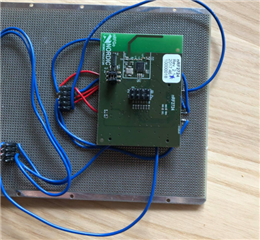
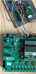
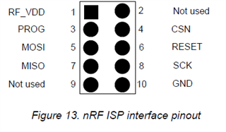
I have successfully programmed the nrf24le1 on the radio module  using the nrf6700 (motherboard) through nrfgo studio. I did so by plugging the radio module into MOD A and MOD B pins on the motherboard. Now, I am trying to use the ISP port on the motherboard to program the radio module. The reason that I am doing this is because I am waiting for my application boards with an nrf24le1 to ship to me so I am practicing using the ISP with the radio module as my "application board". I have setup a circuit that accesses VCC_nrf, MOSI, MISO, RESET, PROG, CSN, SCK, GND on the radio module and connected the pins to the ISP port on  the motherboard.

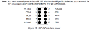
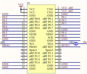
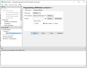
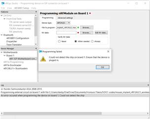
I have also connected VCC pin on the radio module and plugged it into a power supply (VEXT pin on the motherboard) to power the radio module. When I try to program the radio module via nrfgo studio, it says that there is no chip detected for ISP programming. Should I not be using nrfgo studio? I have selected the ISP programming option in nrfgo studio, but there is not an option for the nrf24le1 when I plug in the radio module. should I be using Keil  instead? Am I powering the board wrong? Any help is appreciated.

Thank you for reading this post.

Parents
  • Hello,


    I did so by plugging the radio module into MOD A and MOD B pins on the motherboard. Now, I am trying to use the ISP port on the motherboard to program the radio module.

    Which radio module are you targetting using the ISP port? If its a module that normally fits on MOD A/B or P1/P2 connectors, then its not possible to use the ISP to program them. Then you should use the detected board setup in nRFgo Studio to do so.


    I have setup a circuit that accesses VCC_nrf, MOSI, MISO, RESET, PROG, CSN, SCK, GND on the radio module and connected the pins to the ISP port on  the motherboard.

     If you manually route all these to the external module; it should be OK, but it highly depends on the module as well (if everything is routed directly or through other logic). Which module specifically are you using?


    Should I not be using nrfgo studio? I have selected the ISP programming option in nrfgo studio, but there is not an option for the nrf24le1 when I plug in the radio module. should I be using Keil  instead? Am I powering the board wrong? Any help is appreciated.

    Both Keil C51 and nRFgo Studio can be used to program a module or external board (over ISP), if you choose the correct programming port.

    Do you have a picture of your setup?


    Kind regards,

    Håkon

  • Hi Hakon, 

    Thank you for the response.

    I have manually routed from Pin 1 on the nrf2627 (radio module) using the schematic above. Here is the actual setup:

    1. Here is the manual routing using a pin adapter to Pin 1: 

    2. So the radio module fits on like so. Accessing VCC_nrf, GND, MOSI, MISO, CSN, SCK, PROG, and RESET (the 5x2 pin to the left is what they are routed to. Please ignore the other 4x2 pin): 

    3. Here is how it is connected to the ISP port of the motherboard:

    There is also no indication of what orientation the ISP Port is in. Do you have any way to know? I have tried connecting the pins in either orientation it could be in but neither have worked. This is the only reference I have:

    When I load nRFGo Studio, the motherboard is recognized and there is only an option for ISP programming, shown here:

    When I select "Program", this is the error I recieve:

    Any thoughts on why this may be happening is much appreciated.

  • Hi,


    I would recommend that you ohm from the ISP header on the motherboard to the corresponding pins directly on the nRF24LE1 device to see if they're connected correctly towards the flash-SPI pins on your corresponding package (QFN24/32/48).


    Have you powered the external device? "RF_VDD" does not provide power, its used as a input to the level shifters on the motherboard.


    Kind regards,

    Håkon

  • HI Hakon,

    I have ohm the ISP header to the SPI pins. I am powering the external board as well using the VEXT pins on the general I/O pins on the motherboard. Is that okay? For some reason I am still not getting a signal.

    Kindly,

    Emma

Reply Children
  • Hi Emma,


    BDSL said:
    I have ohm the ISP header to the SPI pins. I am powering the external board as well using the VEXT pins on the general I/O pins on the motherboard. Is that okay? For some reason I am still not getting a signal.

    Verify that the connection to MISO on the header -> the module is connected properly according to the flash SPI in the PS (chapter 6.3.5):

    https://infocenter.nordicsemi.com/pdf/nRF24LE1_PS_v1.6.pdf?cp=12_0_0_0


    So when you have everything connected, ohm from the motherboard to the nRF24LE1 chip (not module!) to ensure its properly routed.

    Also verify that the module is powered up by measuring the voltage the VDD_NRF on the module.


    Kind regards,

    Håkon

  • Hi Hakon,

    Thank you so much for the advice! I am measuring between the VDD pin and the VSS pin of the nrf24le1 on the radio module and noticed that there is only 33mV of power (not enough to power the microcontroller)! I have tried connecting the VCC pin of the radio module (P1 of the 20x2 header for the radio module) to a battery (3.2V) but it is still not getting any power. I have also tried connecting to a VEXT pin on a different I/O header of the motherboard but that does not work (they are only supplying 33mV of power). I have the ISP header of the motherboard connected to the VCC_NRF pin of the radio module 20x2 header which is only for level shifters. Do you know why it isn't getting power? Or how I can give it power?

    Thanks,

    Emma

  • Hi Emma,


    Is the current consumption jumper (P7, just above the  MOD A and MOD B connectors) open? That one should be connected (shorted) to provide VTG.


    Since you do not have a module plugged in right now, the VTG net isn't powered. However, if you have another module; plug that into the motherboard to power the external GPIO headers.

    Alternative is to connect pin 1 and pin 2 together on EXT A (marked as "P5" on the motherboard), which will connect vcc to vtg'.


    Here's the schematic of the motherboard in case you want to look deeper.

    nRF6310_Rev1_4_schem.pdf


    Kind regards,

    Håkon

Related