This post is older than 2 years and might not be relevant anymore
More Info: Consider searching for newer posts

How to adapt the BLE Secure DFU Bootloader to work with nRF52840 dongle?

Hi, you must be sick of me!

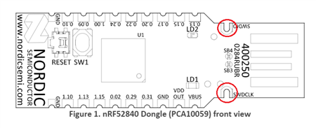
Now that (somehow) I've got the BLE Secure DFU Bootloader to work on my nRF52840 DK board. I'd now like to load it on a nRF52840 dongle pca10059. So I can then work on a buttonless DFU (oh if only this was available out of the box as it surely must be a common use case?)

So, what do I do? Please Slight smile

A question that really concerns me is how to program the dongle.

Programming the DK usually involves an erase option. I've read that doing this with the dongle puts the dongle in a low voltage state and any flashing must be complete before a reset.

How do I ensure that if my attempts don't work at flashing the bootloader that I don't brick the device?

If I do where are the instructions that I can use to recover the dongle using my dk board?

I'm thinking that I'll be okay if I just flash the softdevice and then just keep flashing the bootloader app until it works. Yes there may be some unused code left in the memory map (minimal surely), but hopefully for testing there'll be a "halt" instruction somewhere in the bootloader code  and I'll never reach any garbage? Then when it works I'll do a full erase and flash.

Gordon

Parents
  • I don't think it is going to be that simple sadly.

    I have flashed the s140 softdevice. According to nrFConnect>Programmer that is sitting above the mbr.

    I have built the application with pca10056 changed to pca10059 in the Makefile.

    I have loaded that hex into nrFConnect>Programmer and tried to write it. I get an error saying the bootloader update must be signed. The DFU operation has been cancelled.

    My thinking is that my OTA DFU is signed with my public key, but your Nordic mbr is signed with your key? If so, what do I do?

    The second issue is that I need to find where the operational LEDs are defined i.e. LEDS 1 and 2 for ready to DFU and LEDs 1 and 3 for uploading/flashing. (and change them)

    Also I need to set the button4 + switch on to be the RESET button? or something else.

    Where do I find all this setup? I could spend hours trying to find this?

    Thanks.

  • In fact the Programmer doesn't know anything about my key does it - it's just a hex file, I guess I have to use nrfutil?

    Flashing the app with nrUtil works in terms of flashing, but the memory layout does not look anything like with the DK

    Here is the dongle (no app flashed because it wont, nor advertise DfuTarg)

    Here is the dk board

    Doesn't look the same. In fact the thin green is ordinary blinky app?

  • Hi Gordon,

    gfmoore said:
    The second issue is that I need to find where the operational LEDs are defined

    The LEDs are set in the function dfu_observer in the main.c file og the secure bootloader example. The indexing of the LEDs start with 0 in the code, so BSP_BOARD_LED_0 is the first LED, which will be LED 1 on the dongle. These are general LEDs and are defined in the boards.h file in components/boards/. The dongle only has 2 LEDs, but LED 2 is a multicolored RGB LED, and it is defined in such a way that it counts as three different LEDs, with each color representing one LED. So the general board LEDs will represent the following on the dongle:

    • BSP_BOARD_LED_0 - LED 1
    • BSP_BOARD_LED_1 - LED2 red
    • BSP_BOARD_LED_2 - LED2 green
    • BSP_BOARD_LED_3 - LED2 blue

    The button used to enter DFU mode in the example is defined in sdk_config. Entering DFU mode on button press is enabled with NRF_BL_DFU_ENTER_METHOD_BUTTON:

    #define NRF_BL_DFU_ENTER_METHOD_BUTTON 1

    The dongle only has one user configurable button, SW1. Add the following to sdk_config.h to define SW1 as the button to enter DFU mode:

    #ifndef NRF_BL_DFU_ENTER_METHOD_BUTTON_PIN
    #define NRF_BL_DFU_ENTER_METHOD_BUTTON_PIN 34
    #endif
    gfmoore said:
    In fact the Programmer doesn't know anything about my key does it - it's just a hex file, I guess I have to use nrfutil?

     No, the Programmer does not know about the key. I asked internally about this, and in order to program this example to the dongle you will need to use an external debugger. This is because the bootloader on the dongle requires bootloader updates to be signed, unlike the SoftDevice and application which can be updated using DFU without any form of signing. When you use the Programmer application or nrfutil to program the dongle, you do so over DFU using the bootloader.

    Best regards,

    Marte

Reply
  • Hi Gordon,

    gfmoore said:
    The second issue is that I need to find where the operational LEDs are defined

    The LEDs are set in the function dfu_observer in the main.c file og the secure bootloader example. The indexing of the LEDs start with 0 in the code, so BSP_BOARD_LED_0 is the first LED, which will be LED 1 on the dongle. These are general LEDs and are defined in the boards.h file in components/boards/. The dongle only has 2 LEDs, but LED 2 is a multicolored RGB LED, and it is defined in such a way that it counts as three different LEDs, with each color representing one LED. So the general board LEDs will represent the following on the dongle:

    • BSP_BOARD_LED_0 - LED 1
    • BSP_BOARD_LED_1 - LED2 red
    • BSP_BOARD_LED_2 - LED2 green
    • BSP_BOARD_LED_3 - LED2 blue

    The button used to enter DFU mode in the example is defined in sdk_config. Entering DFU mode on button press is enabled with NRF_BL_DFU_ENTER_METHOD_BUTTON:

    #define NRF_BL_DFU_ENTER_METHOD_BUTTON 1

    The dongle only has one user configurable button, SW1. Add the following to sdk_config.h to define SW1 as the button to enter DFU mode:

    #ifndef NRF_BL_DFU_ENTER_METHOD_BUTTON_PIN
    #define NRF_BL_DFU_ENTER_METHOD_BUTTON_PIN 34
    #endif
    gfmoore said:
    In fact the Programmer doesn't know anything about my key does it - it's just a hex file, I guess I have to use nrfutil?

     No, the Programmer does not know about the key. I asked internally about this, and in order to program this example to the dongle you will need to use an external debugger. This is because the bootloader on the dongle requires bootloader updates to be signed, unlike the SoftDevice and application which can be updated using DFU without any form of signing. When you use the Programmer application or nrfutil to program the dongle, you do so over DFU using the bootloader.

    Best regards,

    Marte

Children
  • Thank you so much for a detailed and informative answer.

    My only issue then is: "you will need to use an external debugger".

    Are you saying I need an external box like a segger? And then I need to solder a connector on to the dongle - that's going to be too expensive for me and beyond my soldering ability - have you seen how small the connector pads are? I don't even know where to buy a socket.

    If I've understood you properly, then this is a disaster. :(


  • Hi,

    You can use your nRF52840 DK as the external debugger, by using the debug out connector on the DK as explained here, so you do not need to buy an additional debugger. On the DK you can simply connect a 10-pin cable to P19. There are two connection points for the SWD interface on the backside of the dongle, P1 and J2, but you will unfortunately have to solder. For P1 you only need a standard 2x5-pin header with a 1.27mm pitch, which you can get rather cheap, while for J2 you can use a TC2050 cable from Tag-Connect. 

    You also have another option for connecting to the Dongle, which is to connect to SWDIO and SWDCLK directly. This still requires soldering, but you might find this to be easier than soldering the connectors on the backside, and the only things you need in addition to the external debugger (nRF52840 DK) are wires. You can do this by soldering wires directly to SWDIO and SWDCLK on the dongle. I have marked the plated half-holes where you will have to solder the wires on the picture below.

    You can then use P20 as debug out connector on the DK and connect the SWDIO and SWDCLK wires to their corresponding connectors on the DK.

    If you have not already, I recommend reading the section "Using an external debugger" in the guide I linked you earlier before you start programming the dongle using this, as this is where the warnings about the UICR and the voltage on the dongle is important.

    I know this requires more work than simply using the bootloader on the dongle, but I hope some of the alternatives will work for you so you will be able to program the example on your dongle!

    Best regards,

    Marte

Related