This post is older than 2 years and might not be relevant anymore
More Info: Consider searching for newer posts

Rerouting AT interface for power measurement using external supply

Hi there,

We received your devkits on Friday, 25th of June and started evaluation of the modules this morning (Magnus Pederson and Brian Kim @ Nordic arranged the devkits for us). We are able to successfully connect to the network and do current measurements. Since we are on a tight schedule, I was hoping you could assist with the following simple issue:

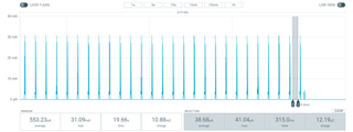
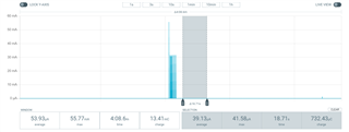
We will be using a supply voltage of around 3.3 - 3.6V, and would thus want to evaluate the power consumption at that supply. For this, we add an external supply to P21 and bridge SB20. We then add a current meter (Nordic PPK2) to P22. We do however only want to evaluate the power profile of the nRF9160 chip, and not the interface MCU. We thus put SW6 in the "right" position.

When this is the case, the UART interfaces are not available on the USB connector. Also when having the USB cable connected, the supply voltage is 5V, so we do not want to have the USB cable connected at all. Thus to communicate via the serial interface with the nRF9160, we will need to reroute the UART pins to the external connectors. We can then use a serial-to-usb adapter to communicate using a simple terminal program (TeraTerm).

Could you please advise as to what would be the quickest way to do this? Which UART port is the AT interface (UART0/1/2)? I guess we will also have to disable HW flow control for this test as our Serial to USB adapter has only a TX, RX and GND wire.

We are reaching out simply to speed up the evaluation process.

Thanks in advance!

Kind regards,

Frikkie Badenhorst

Parents Reply Children
  • Thanks Stian, we have a fully configurable test network and base station (Amarisoft Callbox Mini), so we force the network to basically accept any timer request by the UEs.

    When using the 5 minute TAU wakeup and 0 minute active time as you mentioned, I can see the device going into a 3uA state. 

    However, as a test I am setting the following:

    Active timer: 30minutes 

    TAU: 7 hours

    eDRX cycle: 655sec (+- 11 minutes)

    PTW: 5.12 sec

    From this, 

    This is probably due to the SIM card being active. The SIM is active if the DRX interval (the spikes you see every 640ms (?)) is less than 1 minute

    I would think that the SIM should be deactived since the DRX cycle is larger than 1minute, but we still see the 39uA current after the PTW is complete:

    Is this expected behaviour? Then I guess that the SIM card is always active during the active time, regardless of the DRX cycle?

  • Sorry, forgot to mention, you need to set the power saving profile. Use the AT%XDATAPRFL command and set the level to 0.

    The power saving level has an effect on the shutdown of the UICC during Extended Discontinuous Reception (eDRX) cycles. On power level 0, the modem deactivates the UICC if the eDRX period is longer than 60 seconds and UICC deactivation is allowed through EF-AD under USIM ADF. The modem activates the UICC and performs the necessary checks before setting up any signaling or data connections with the network. Otherwise, the UICC is not activated because of modem functionality.

    On power levels 1–4, the modem deactivates the UICC if the eDRX cycles are longer than 10 minutes. The UICC is activated before any signaling or data connections are set up with the network and when waking up from eDRX. This means that the UICC is deactivated and activated at every eDRX cycle.

  • The text marked in red in the previous answer is kind of important as well. This field has to be set in the SIM, which it's usually not by default. If you have a regular test-SIM for your callbox, you probably have the ADM key and can change this field.

  • Ok for now we are still not able to get it in a lower power between DRX cycles. Will have to look into the setting of the field on the SIM. When testing a modem from a different manufacturer however, we are not seeing this, which makes me wonder if it is indeed the SIM.

    Nonetheless for now we can work with this value we are seeing as a test.

    Thanks for all your assistance, Stian.

  • Hi Stian, I have identified another important question:

    According to the MQTT AT command used with this Serial LTE Modem app allows only a max publish payload of 576 bytes. Is this only limited by the application itself and can be increased by simply adjusting a variable, or is this a hard limitation of the modem? I cant think 576 is the max payload, thus I believe it is the former.

    I also believe we will be able to specify our own MQTT keep-alive time, and not the default 60 seconds?

    I am asking this on this ticket, as this is still related to the hex file you prepared for us!

    Thanks!

Related