This post is older than 2 years and might not be relevant anymore
More Info: Consider searching for newer posts

SCH&PCB Layout Review nrf52833

We plan to design a module that wirelessly connects via the nRF52833 chip with RF amplification, 2 PWM outputs and multiple
Digital I/O interfaces,One ADC interface and Communication serial port。Pin-specific functions make schematic files visible

Questions:

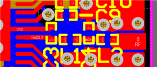
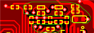
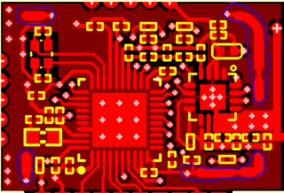
1. Please help check the rationality of the schematic design and PCB layout. In particular, the RF output and PCB antenna section, and give reference recommendations.
2.can you give nRF chip RF signal and PA matching network (C20) selection point recommendations?
3.RF output and antenna part of the capacitor selection of what advice?
Note: The module is customized and the module pins and dimensions are non-changeable。


Thanks! nRF52833_QDAA.rar


Parents
  • Hi.

    I have take a look at the schematic and layout, and have the following comments:

    1. C10 must only be connected to the VSS_PA pin and the center pad, see the reference schematic:

    The rest of the radio matching network needs to be moved closer to the chip. A continuous ground should also be directly under the RF path, I would recommend removing the keep out area on the internal ground layer to achieve this. Both under the radio matching network and under the RF line from the front end module to the antenna.

    2. The trace connecting the radio matching network to the front end module should be a 50 Ohm transmission line. The recommended line is a grounded coplanar waveguide.

    3.  The components close to the RF line should be moved further from the line, such that good ground pour separates them from the line.

    4. There must be a ground pour on the top layer, There should be good ground connection around the RF lines. A ground pour is especially if these pads(marked in blue) are connections to a RF shield.


    can you give nRF chip RF signal and PA matching network (C20) selection point recommendations?

     The value of C20 must be determined by radio tuning. Until that is performed it should be left N.C.


    3.RF output and antenna part of the capacitor selection of what advice?

     The values of C23, L5, C24, C19 and C25 must also be determined in the radio/antenna tuning process. L5 and C19 should be populated with 0Ohm resistor and C23, C24 and C25 left N.C until the tuning is performed.

    We provide free radio and antenna tuning services. When the prototype boards are produced we can do radio measurements and tuning of the radio and antenna matching networks.

    Best regards,

    Bendik Heiskel

Reply
  • Hi.

    I have take a look at the schematic and layout, and have the following comments:

    1. C10 must only be connected to the VSS_PA pin and the center pad, see the reference schematic:

    The rest of the radio matching network needs to be moved closer to the chip. A continuous ground should also be directly under the RF path, I would recommend removing the keep out area on the internal ground layer to achieve this. Both under the radio matching network and under the RF line from the front end module to the antenna.

    2. The trace connecting the radio matching network to the front end module should be a 50 Ohm transmission line. The recommended line is a grounded coplanar waveguide.

    3.  The components close to the RF line should be moved further from the line, such that good ground pour separates them from the line.

    4. There must be a ground pour on the top layer, There should be good ground connection around the RF lines. A ground pour is especially if these pads(marked in blue) are connections to a RF shield.


    can you give nRF chip RF signal and PA matching network (C20) selection point recommendations?

     The value of C20 must be determined by radio tuning. Until that is performed it should be left N.C.


    3.RF output and antenna part of the capacitor selection of what advice?

     The values of C23, L5, C24, C19 and C25 must also be determined in the radio/antenna tuning process. L5 and C19 should be populated with 0Ohm resistor and C23, C24 and C25 left N.C until the tuning is performed.

    We provide free radio and antenna tuning services. When the prototype boards are produced we can do radio measurements and tuning of the radio and antenna matching networks.

    Best regards,

    Bendik Heiskel

Children
No Data
Related