This post is older than 2 years and might not be relevant anymore
More Info: Consider searching for newer posts

How to evaluate GPS sensitivity of nRF9160 if using active antenna?

Dear Devzone,

At the moment, We do not have methods to measure the GPS sensitivity of our products based on nRF9160.

We are using an active antenna with LNA gain 16dB, NF 1dB.

The Schematic for the GPS part is like below.

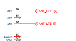
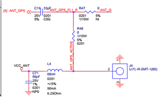
We apply a Simulated GPS signal directly to J4. And the minimum level where nRF9160 still could fix coordinates is -129dBm.

Could we use this result including test report of external LNA (from Antenna active) to infer the sensitivity of the device? If yes, how to infer?

Thank you and Best regards,

Ngoc Nguyen

Parents
  • Dear Jonathan,

    Before I could do some checking steps as you mention, Could you tell me what the expected minimum level is in the case I apply GPS signal directly to GPS pin?

    And in my case, Could I refer that the sensitivity of the device is -129dBm -16dB (LNA gain) = -145dBm?

    Thanks and regards,

    Ngoc Nguyen

  • Ngoc Nguyen said:
    And in my case, Could I refer that the sensitivity of the device is -129dBm -16dB (LNA gain) = -145dBm?

    No, sensitivity is not defined like that. Please see https://infocenter.nordicsemi.com/topic/ps_nrf9160/gps.html#overview for GPS sensitivity of nRF9160. 


    Regarding external LNA, the purpose of it is to compensate/minimize the impact of RF chain after the external LNA itself, i.e. minimize the negative impact of any lossy elements in RF chain such as BPF (recommended), RF routing itself, possible test connectors etc., and noise figure of nRF9160 itself. How the physics go, is defined by Friis formula;


    From formula you can see, the external LNA's noise figure(/factor) (F1) dominates in total noise (Ftotal) as the next elements noise is divided by gain of first element (external LNA gain) i.e. making the relative contribution of rest of elements (F2, F3,..) in RF chain much smaller to total noise. 

    Regards,
    Jonathan

  • Dear Jonathan, 

    Thank you for answering my question, and consolidating my knowlege. 

    However, I still do not know how to measure and confirm that our device could reach GPS sensitivity as specified in infocenter.nordicsemi.com/.../gps.html

    By the way, I am quite confused In the case of nonsignaling mode as guided in https://infocenter.nordicsemi.com/index.jsp?topic=%2Fps_nrf9160%2Fgps.html&anchor=overview, 

    Moreover, why is the recommended signal level for GPS mode testing -100 dBm?

    Brs,

    Ngoc Nguyen

  • Hi Ngoc.

    The feedback from the expert on your case:
    Having a look at the schematic one relatively easy modification could be tried: Remove the R47 connecting onboard LNA as there is a risk that the thermal noise rise at point between R47 and C19 with amount of onboard LNA gain (if active), thus decreasing SNR (or C/N0) at RFIC's GPS input. Active antenna gain of 16dB may not over come the risen thermal noise at the point in question. Another option is to disable onboard LNA by SW-control, but it may not be as good solution as removing R47 due to LNA output circuit still loading the external active antenna path.

    Non-signaling CW test (positive SNR test) is mainly meant for production to verify HW connections validity, but it can be used for RFHW debugging as well with given test signal and GPS SNR limit recommendations in documentation.


    Edit:
    Update/correction on my previous comments: I was too quick to talk about onboard external LNA, it looks like not being there, but filter only instead (No onboard ext-LNA??). Then in this case comment "removing R47" should improve the sensitivity. Also It's good to keep in mind that PS's GPS sensitivity figure apply when external LNA with NF 2dB max and gain 16dB min from LNA input to SIP's GPS input, i.e. conducted measurement directly at external LNA (with mentioned specs) input.


    Regards,
    Jonathan

  • Additional info:
    Recommendation to use -100dBm "GPS" (in this test CW) signal level is to verify end-product design (noise from LEDs, active ICs, DCDCs, other routing, etc.) is not causing noise leaking into nRF91 GPS input and issues to GPS performance (typical issue in end-products). If GPS signal level would be high in testing, noise from aforementioned sources might not cause issues but in real life field situation as GPS signal levels are typically low, issue would became visible.

    For simplified GPS sensitivity (alike) testing CW SNR test can be used, where only CW signal generator is needed. See https://infocenter.nordicsemi.com/index.jsp?topic=%2Fnwp_034%2FWP%2Fnwp_034%2Fnwp_034_nonsignal_gps.html&cp=2_0_7_3_2_4_0_1_2 for CW SNR test. CW signal generator can be connected directly to nRF91 GPS pin at e.g. -100dBm level, then expected SNR is as in plot "No Ext-LNA". 


    For real GPS sensitivity testing signal generator capable of GPS constellation is needed.

    Regards,
    Jonathan

Reply Children
No Data
Related