Hello Nordic Wizards,
We are in the final throws of a project preparing to go to market. However we have identified a "strange" problem.
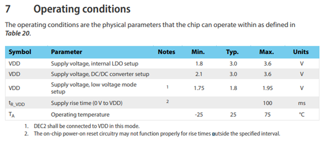
if the batteries driving the board power are allowed to fully discharge, once they start recharging, plugging/unplugging the board from a charger resets the board and may lock the code up in an unknown state. If the board is reprogrammed, this condition stops, until the next time the battery/board is fully discharged. Has anyone see these types of problems with this chip, and/or can you point me to a prospective solution.
Thank you kindly
Robin @ TL