This post is older than 2 years and might not be relevant anymore
More Info: Consider searching for newer posts

Problem with I and Q Samples During the Reference Period of CTE Packets

Hi

As described in this white paper: https://infocenter.nordicsemi.com/pdf/nwp_036.pdf during the reference period of CTE signals, 8 samples are taken. These samples contain both "I" and "Q" elements of signal which has different phases relatively.

I have captured the reported "I" and "Q" samples using the samples provided by SDK:

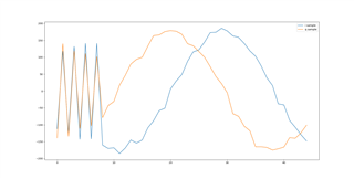
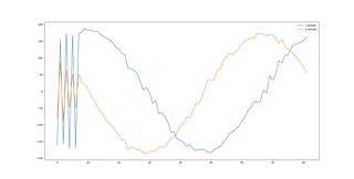
For the reference period, I can not see any phase difference between "I" and "Q" elements (while it should be different). I have visualized the data and you can see the result in the below images:

IQ samples with 2us switching slots and using PCB antenna:
IQ samples with 1us switching slots and using PCB antenna:
IQ samples with 1us switching slots and using array antenna:
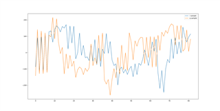

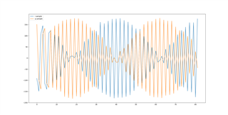
As you can see, in all conditions, the reference period has the similar behavior. I have plotted a third party product which uses the CTE packets and you can see the visualized data here,
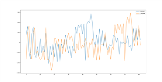
Obviously the "I" and "Q" samples are in different phases during the reference period. What is wrong in the above nRF examples?

Regards,

Saleh

Parents
  • Hi Saleh

    I'm guessing that your locator device is not using an antenna array, as receiving this data with only one antenna will result in a stable phase because there is only one antenna receiving these samples.

    Best regards,

    Simon

  • Hi Simonr

    As described in the this whitepaper: https://infocenter.nordicsemi.com/pdf/nwp_036.pdf , part 4, Table 4: Antenna switching settings, same antenna has been used during the "reference period" , so despite of using antenna array or pcb antenna, similar behavior is expected during this period.

    Anyway the first two images are captured by pcb antenna, the third one has captured using the antenna array and the problem exist.

    To ensure about this problem, I executed the third party implementation (which our algorithm can calculate the transmitter angle based on its results) with the pcb antenna on nRF52833-DK (same as what I have used to run Zephyr examples) ad you can see the results here:

    Obviously the "I" and "Q" samples have different phases in the reference period of CTE signal.

  • Hi Saleh,

    I am currently using 52833-DK to try to output IQ sample plot, but I cannot output the diagram like yours. Can you please provide the corresponding code including algorithm or filtering method?

  • Hi Louis

    This is simply plotting the IQ samples reported by the MCU without any modification. Print the IQ samples using UART2USB line and then store the result in a file. In a for loop, go over the IQ samples and print them:

    printf("%i,%i, i_val, q_val)

    Then open the file that you've stored the IQ log by a python script and plot the numbers:

    import matplotlib.pyplot as plt
    
    IQ_LOG_FILE = "iq_raw_log/iq.txt"
    
    
    def read_file_to_lists(file_name):
        with open(file_name, 'r') as f:
            # Read each line, split the string by spaces, and convert to integers
            return [list(map(int, line.split())) for line in f]
    
    
    def plot_iq(samples):
        i_sample = samples[::2]
        q_sample = samples[1::2]
        plt.plot(i_sample, label='I')
        plt.plot(q_sample, label='Q')
        plt.legend()
        plt.show()
    
    
    if __name__ == '__main__':
        lists_from_file = read_file_to_lists(IQ_LOG_FILE)
        plot_iq(lists_from_file[2])
    

    It assumes the IQ is stored into the file in a format like this:

    i11, q11, i12, q12, ...., i1n, q1n
    i21, q21, i22, q22, ...., i2n, q2n

    Each line has the IQ samples of one single CTE capture, I comes first and then Q, and they are seperated by comma

Reply
  • Hi Louis

    This is simply plotting the IQ samples reported by the MCU without any modification. Print the IQ samples using UART2USB line and then store the result in a file. In a for loop, go over the IQ samples and print them:

    printf("%i,%i, i_val, q_val)

    Then open the file that you've stored the IQ log by a python script and plot the numbers:

    import matplotlib.pyplot as plt
    
    IQ_LOG_FILE = "iq_raw_log/iq.txt"
    
    
    def read_file_to_lists(file_name):
        with open(file_name, 'r') as f:
            # Read each line, split the string by spaces, and convert to integers
            return [list(map(int, line.split())) for line in f]
    
    
    def plot_iq(samples):
        i_sample = samples[::2]
        q_sample = samples[1::2]
        plt.plot(i_sample, label='I')
        plt.plot(q_sample, label='Q')
        plt.legend()
        plt.show()
    
    
    if __name__ == '__main__':
        lists_from_file = read_file_to_lists(IQ_LOG_FILE)
        plot_iq(lists_from_file[2])
    

    It assumes the IQ is stored into the file in a format like this:

    i11, q11, i12, q12, ...., i1n, q1n
    i21, q21, i22, q22, ...., i2n, q2n

    Each line has the IQ samples of one single CTE capture, I comes first and then Q, and they are seperated by comma

Children
No Data
Related