
Hi nRF support team,
What do I need to do if I want to use the precise delay of NS, now the delay error is very large.
thanks
Hi nRF support team,
What do I need to do if I want to use the precise delay of NS, now the delay error is very large.
thanks
Hi
You get the most accurate timing by running a TIMER peripheral with prescaler 0. Then you get a timer frequency of 16MHz, which equals an interval of 62.5ns.
What kind of accuracy do you need?
If you are triggering a measurement from the software keep in mind that your code might be interrupted by other parts of the system.
If you want to measure hardware events you can use the PPI controller to connect the hardware events to the timer directly, which ensures much more consistent timing.
Best regards
Torbjørn
Hi,Torbjørn
Thank you for your reply
I need the software to measure, and the delay accuracy is around 1us. Do you have the peripheral example of Timer? I am a novice, and I don't know how to configure it
thanks
Hi
Since you are using NCS and Zephyr it is possible to make accurate timing measurements by reading the system clock directly, like described here:
https://developer.nordicsemi.com/nRF_Connect_SDK/doc/0.3.0/zephyr/kernel/timing/clocks.html#measuring-time-with-high-precision
Can you try this method and see if it give you satisfactory results?
Best regards
Torbjørn
Hi,Torbjorn
Thank you for your reply
I have solved the problem of precise delay, but I have a new problem.
I have a piece of code that doesn't need any external interrupts or events to interrupt, but I use the __disable_irq() function before that and then __enable_irq() function after that. But it did not achieve the desired effect. If I don't call __enable_irq() the effect of turning on interrupts is what I want
1. Is there a problem with the __disable_irq() function? Why does closing interrupt and then opening interrupt affect the code in the middle? Is there any task or interrupt not closed successfully?
2. Does my problem have something to do with the frequent switching of the interrupt switch? If so, how do I fix it?
I am looking forward to your reply. This question is urgent
Thank you very much
Hi
What about using irq_enable() or irq_disable() instead?
These are the standard Zephyr functions for enabling and disabling interrupts:
https://docs.zephyrproject.org/latest/reference/kernel/other/interrupts.html
If this doesn't work, can you show me the code that is not behaving correctly?
Best regards
Torbjørn
Hi
Torbjørn
Here's my code:
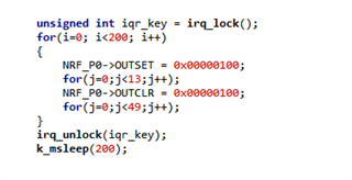
Since I was using NCS 1.6.0, I replaced it with irq_lock(). Through the for (I = 0; i<200; I++) to flip the IO port, but the waveform seen with the oscilloscope is unstable. If only irq_lock() is executed and irq_unlock() is not executed, then the waveform is normal. The next two videos are my waveforms.
May I ask what causes this? Looking forward to your reply
Thank you very much
Hi
Torbjørn
Here's my code:
Since I was using NCS 1.6.0, I replaced it with irq_lock(). Through the for (I = 0; i<200; I++) to flip the IO port, but the waveform seen with the oscilloscope is unstable. If only irq_lock() is executed and irq_unlock() is not executed, then the waveform is normal. The next two videos are my waveforms.
May I ask what causes this? Looking forward to your reply
Thank you very much
Hi
A couple of thoughts:
1) Are you running any radio protocol (like Bluetooth) in the background?
The timing shift you see on the scope might be caused by the external 32MHz clock being enabled and disabled by some other module in your code.
The internal high frequency clock can have a frequency drift of 5% and more, and if you switch between that and the external clock you can see this type of shift.
The solution to this problem is to request the 32MHz clock to be running all the time.
2) Is your end goal to toggle a pin at a specific frequency?
If so I would strongly recommend using the PWM module, or a combination of the TIMER, PPI, and GPIOTE modules. Then you can have the pin toggled automatically, without having to bit bang everything.
Best regards
Torbjørn
Hi,Torbjørn
Thank you for your reply
1.What do I need to do to keep 32M on when I send data? Is there this API function? Because of the need for low power consumption, I can't always turn it on. Only turn it on before sending data, and turn it off after sending data, ok?
2. Since the code segment controlling IO is not periodic, I cannot use PWM.
Hi
1. You could have a look at the clocks_start(..) function from the ESB example:
https://github.com/nrfconnect/sdk-nrf/blob/master/samples/esb/ptx/src/main.c#L58
2. Do you happen to have a description of how the IO pulses are generated?
The PWM module is quite flexible, and can be configured in a way where both the duty cycle and frequency can change dynamically, so it is possible that there is a way to do this using PWM.
Best regards
Torbjørn
Hi,Torbjørn
Thank you for your reply
1.I tested the clock at 32M and the exception did not improve.
2.Is there such a variable cycle PWM driver routine?
Looking forward to your reply
Hi
2. Yes, please read the Decoder with EasyDMA chapter available here.
Essentially, when you set the DECODER.LOAD mode to WaveForm, you can have the PWM interval/frequency updated dynamically based on values in RAM.
Values 0, 1 and 2 in the PWM buffer will set the duty cycle for up to 3 GPIO outputs, while value 3 sets the common countertop value for the three output channels. The PWM frequency is defined by the PWM base frequency (configurable through the PRESCALER register) divided by the countertop value, and in this mode you can have the frequency change for every single pulse.
For an example of how to use the nrfx_pwm driver in NCS you can have a look at this example.
It doesn't use the WaveForm LOAD setting, but you can change the example to test this out.
Best regards
Torbjørn

