This post is older than 2 years and might not be relevant anymore
More Info: Consider searching for newer posts

nRF5340 + nRF21540 connection

Hi,

I have questions about the connections between the nRF5340 and the FEM nRF21540.

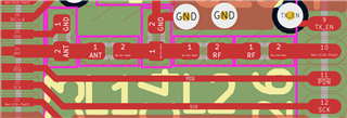
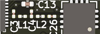
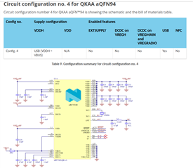
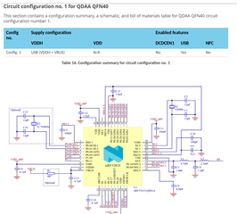
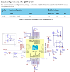
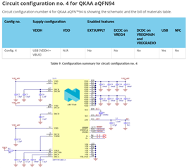
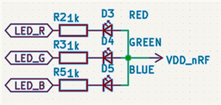
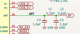
The nRF5340 has these components:

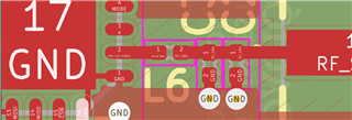
And the nRF21540 has this component:

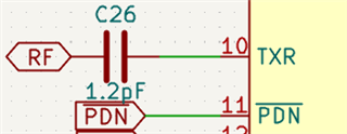
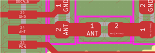
I wonder if C3,C4,L1 and L2 are needed between these two IC.

Wouldn't be enough just used the C26?

I am using a single antenna.

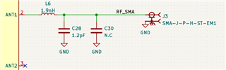
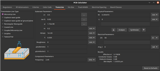
The C28, C30 and L6 are needed to match the antenna impedance of 50Ohms, but I am not sure if it's actually needed to match impedance between ICs.

The same questions goes for the nRF52833 + nRF21540.

Any suggestions?

Thanks and best regards,

Jose Pablo Castro,

Parents
  • Hi Jose

    All the components shown on the nRF5233 and nRF21540 schematics are mandatory. Any antenna matching components comes in addition to L6, C28 and C30. 

  • Hi ketijo,

    If I understand you correctly, there's no need to add or remove any component (Capacitance or Inductance).
    Am I right?

    I got another question regard to PCB board.

    I am placing all components as close as possible, including the SMA Connector like this:

    Between nRF52833 and nRF21540:

    3D View (Kicad Nightly)


    And between nRF21540 and SMA Connector:

    3D View:

    The stack-up is this:

    And the width calculation for 50 Ohms is this:

    Is this components placement and distance correct or should I increase the distance between components?

    I am using the exact width of 0.355473 mm except between nRF52833 pin 24 (ANT) and C3 (The actual size is 0.3 mm)


    as far as I understand the width is ok for 50 Ohms but I have my doubts especially if there could be any problem between C3 and pin 24 of nRF53833.

    Any suggestion or recommendation?

    Thanks and Best Regards,

    José P. Castro

Reply
  • Hi ketijo,

    If I understand you correctly, there's no need to add or remove any component (Capacitance or Inductance).
    Am I right?

    I got another question regard to PCB board.

    I am placing all components as close as possible, including the SMA Connector like this:

    Between nRF52833 and nRF21540:

    3D View (Kicad Nightly)


    And between nRF21540 and SMA Connector:

    3D View:

    The stack-up is this:

    And the width calculation for 50 Ohms is this:

    Is this components placement and distance correct or should I increase the distance between components?

    I am using the exact width of 0.355473 mm except between nRF52833 pin 24 (ANT) and C3 (The actual size is 0.3 mm)


    as far as I understand the width is ok for 50 Ohms but I have my doubts especially if there could be any problem between C3 and pin 24 of nRF53833.

    Any suggestion or recommendation?

    Thanks and Best Regards,

    José P. Castro

Children
Related