This post is older than 2 years and might not be relevant anymore
More Info: Consider searching for newer posts

Verification for schematic for custom Board

Hi,

We are design custom Board using nRF52840 SOC.

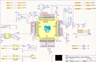
  1. We are operating it in Normal mode, using internal DCDC converter
  2. We have used configuration 5 from reference design
  3. From reference design we have removed NFC pins connection and USB connection because we do not need it in our design
  4. We will be programing our custom board using nRF52840 DK
  5. We have attach led using load switch at P0.15
  6. We have attach buzzer using load switch at P0.16
  7. We have attach button at P0.24
  8. We have taken antenna schematic from nRF52840DK hardware files and remove external connector. Have we done it correctly?
  9. Have we connected reset button correctly?

I am attaching the Schematic design for our board can you verify it if it is correct or we are missing something, If it is unclear in picture I can also attach schematic file

Thanks in advance
Regards,

Moghees Bin Zahid

Parents
  • Hi Moghees,

    Thanks for the detailed information.

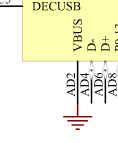
    When not using USB you can ground VBUS as seen in circuit configuration no. 6:

    We have taken antenna schematic from nRF52840DK hardware files and remove external connector. Have we done it correctly?

    Yes, but whether or not you only need antenna matching component C23 depends on what type of antenna you are planning on using. If you are copying the antenna layout from the nRF52840 DK, then one antenna matching component will probably work fine, otherwise we'd recommend a pi-network of antenna matching components for greater versatility in tuning the antenna.

    The reset button is connected correctly.

    What's just as critical is the PCB layout, so feel free to share that when you have it done and we can take a look at it.
    If you follow the reference layout exactly you shouldn't have any issues.

    Best regards,

    Martin S.

  • Thanks for the reply Martin. Firstly I want to appreciate the documentation of Nordic.  

    Yes, but whether or not you only need antenna matching component C23 depends on what type of antenna you are planning on using. If you are copying the antenna layout from the nRF52840 DK, then one antenna matching component will probably work fine, otherwise we'd recommend a pi-network of antenna matching components for greater versatility in tuning the antenna.

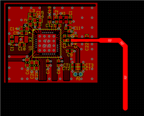
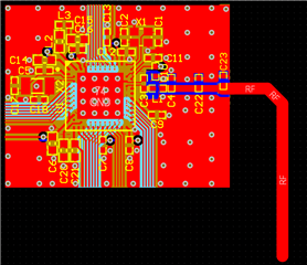
    I will be using same Antenna used in nRF52840DK. I want to ask can I copy antenna for nRF52840DK PCB layout and placed it on my PCB layout? If yes then in place of connector that is connected for external antenna of DK I should just extend antenna layout?

    I have few others questions:
    1. Can I remove net names and wires that I am not using in our design?

    2. It is first time I am designing PCB using nRF52840 SoC. Can you recommend me document that I can follow?

    3. Can I use reference layout PCB layout and extend it for our PCB?


    Regards,
    Moghees Bin Zahid

  • HI Moghees,

    Moghees said:
    I will be using same Antenna used in nRF52840DK. I want to ask can I copy antenna for nRF52840DK PCB layout and placed it on my PCB layout?

     Yes you can.

    Moghees said:
    If yes then in place of connector that is connected for external antenna of DK I should just extend antenna layout?

     Yes, you can just remove the MM8130 connector with switch and use an unbroken transmission line from the radio matching network to the antenna matching network (capacitor C23 in your case)

    Moghees said:
    Can I remove net names and wires that I am not using in our design?

     Yes.

    Moghees said:
    It is first time I am designing PCB using nRF52840 SoC. Can you recommend me document that I can follow?

    Here is some documentation for the reference circuitry of the nRF52840 itself, and here you can download reference layout for the nRF52840 itself, and here is the hardware files for the nRF52840 Development Kit which you can use as reference. You can also search for documentation and reference here on DevZone, there are a lot of cases with tips and guides to creating a custom PCB with an nRF52840.

    Moghees said:
    Can I use reference layout PCB layout and extend it for our PCB?

     Yes you can.

    Best regards,

    Martin S.

  • Thanks for the reply. I am not closing this discussion because after completing PCB designing I will share my design here. So that you can review it

Reply Children
Related