This post is older than 2 years and might not be relevant anymore
More Info: Consider searching for newer posts

Verification for schematic for custom Board

Hi,

We are design custom Board using nRF52840 SOC.

  1. We are operating it in Normal mode, using internal DCDC converter
  2. We have used configuration 5 from reference design
  3. From reference design we have removed NFC pins connection and USB connection because we do not need it in our design
  4. We will be programing our custom board using nRF52840 DK
  5. We have attach led using load switch at P0.15
  6. We have attach buzzer using load switch at P0.16
  7. We have attach button at P0.24
  8. We have taken antenna schematic from nRF52840DK hardware files and remove external connector. Have we done it correctly?
  9. Have we connected reset button correctly?

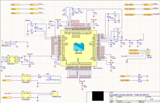
I am attaching the Schematic design for our board can you verify it if it is correct or we are missing something, If it is unclear in picture I can also attach schematic file

Thanks in advance
Regards,

Moghees Bin Zahid

Parents
  • Hi Moghees,

    Thanks for the detailed information.

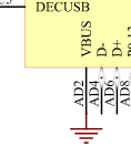
    When not using USB you can ground VBUS as seen in circuit configuration no. 6:

    We have taken antenna schematic from nRF52840DK hardware files and remove external connector. Have we done it correctly?

    Yes, but whether or not you only need antenna matching component C23 depends on what type of antenna you are planning on using. If you are copying the antenna layout from the nRF52840 DK, then one antenna matching component will probably work fine, otherwise we'd recommend a pi-network of antenna matching components for greater versatility in tuning the antenna.

    The reset button is connected correctly.

    What's just as critical is the PCB layout, so feel free to share that when you have it done and we can take a look at it.
    If you follow the reference layout exactly you shouldn't have any issues.

    Best regards,

    Martin S.

  • Hi Martin,

    How are you?

    After successful testing of version 1 of the board, we are going to design version 2. Requirements are:

    1. It should be battery operated, we will be using pair of 4xAA cells in series
    2. It should be capable of Battery Monitoring (using pin P0.29/AIN5)
    3. Interface for motor control (using pin P0.20 and P0.22)
    4. Interface to attach Reed switch (using pin P0.13)
    5. Interface to attach 2 micro Switch (using in P0.24 and P0.25)

    Can you kindly verify Schematics and answer my following questions:

    1. Are GPIOs mentioned above fine or should I use other ones?
    2. I am using the same Ferrit Bead for Battery as of USB-C, is it ok?
    3. As I am operating nRF52840 SoC on 3V, the ADC channel can only take a max of 3V as input, for that purpose I am using Zener Diode can you verify Battery Monitoring Circuit? (Zener Datasheet)
    4. Now we have 2 power sources i.e, 5V from USB-C and 6V from the battery, for source selection I am using Schottky Barrier Diode Oring Scheme, can you verify its circuit? (Schottky Barrier Diode Datasheet)
    5. I am using Linear voltage regulator HT7830 for getting 3V to run nRF52840 SoC. (Ht7830 Datasheet)
    6. I am exposing pins to connect the micro and Reed switch, is it ok?
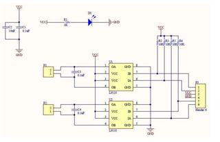
    7. Do you recommend adding capacitors with motor driver IC? As shown in following Image:

    Note: Please find attached a PDF file containing Schematic files for LL_V2.0

    Thanks in advance


    Regards,
    Moghees Bin Zahid

    LL_V2.0_Schematics.pdf

  • Hello Moghees,

    I have a significant work load at the moment, but I'll get to your board soon, you'll hear from me tomorrow at the latest.

    At the same time I have to mention that we rarely do full schematic reviews, we just don't have the resources for it, we focus on the nRF-device and RF front end (matching circuitry and antenna layout).
    If the board is fairly simple we can sometimes look at the rest as a courtesy, but it just becomes too time consuming to do it for every customer design.

    Best regards,

    Martin S.

Reply
  • Hello Moghees,

    I have a significant work load at the moment, but I'll get to your board soon, you'll hear from me tomorrow at the latest.

    At the same time I have to mention that we rarely do full schematic reviews, we just don't have the resources for it, we focus on the nRF-device and RF front end (matching circuitry and antenna layout).
    If the board is fairly simple we can sometimes look at the rest as a courtesy, but it just becomes too time consuming to do it for every customer design.

    Best regards,

    Martin S.

Children
No Data
Related