This post is older than 2 years and might not be relevant anymore
More Info: Consider searching for newer posts
This discussion has been locked.
You can no longer post new replies to this discussion. If you have a question you can start a new discussion

HFCLK timer issue

Hi Nordic Engineers,

I have few queries over HFCLK 16 MHz timer.

I am using nrf52840 custom board. IDE - segger embedded studio

#define TIME_IN_US  2600


/**
 * @brief Handler for timer events.
 */
void timer_led_event_handler(nrf_timer_event_t event_type, void* p_context)
{
      switch (event_type)
      {
          case NRF_TIMER_EVENT_COMPARE3:
              timerenabled = 1;
              if(!cal_HR_ir_enabled)
              {
                  DisableHRMLed();       //Disabling RED and Enabling IR
                  EnableHRMLed(HR_IR_LED);
                   //printf("Timer IR\r\n");
              }
              else if(!cal_HR_red_enabled)
              {
                  DisableHRMLed();       //Disabling IR and Enabling RED
                  EnableHRMLed(HR_RED_LED);
                   //printf("Timer RED\r\n");
              }
              break;

          default:
              //Do nothing.
              break;
      }
}

void enable_HR_LED_timer(void)
{ 
      uint32_t time_ticks;
      uint32_t err_code = NRF_SUCCESS;

      //Configure TIMER_LED for generating simple light effect - leds on board will invert his state one after the other.
      nrf_drv_timer_config_t led_timer_cfg = NRF_DRV_TIMER_DEFAULT_CONFIG;
      err_code = nrf_drv_timer_init(&TIMER_LED, &led_timer_cfg, timer_led_event_handler);
      APP_ERROR_CHECK(err_code);

      //Time(in microseconds) between consecutive compare events.
      time_ticks = nrf_drv_timer_us_to_ticks(&TIMER_LED, TIME_IN_US);

      nrf_drv_timer_extended_compare(
           &TIMER_LED, NRF_TIMER_CC_CHANNEL3, time_ticks, NRF_TIMER_SHORT_COMPARE3_CLEAR_MASK, true);

      nrf_drv_timer_enable(&TIMER_LED);
}

I have enabled HFCLK timer and able to reach timer callback.

The problem is...If I set the Timeout as 2600 us, it seemed only timer callback was running (not even while(1) ) 

But in 2700 us or greater, each and every functionalities were working fine.

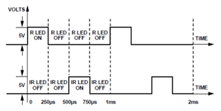
I have to generate ~250us time delay. 

I have attached my code snippet and I am using Timer 3

Looking forward for your suggestion.

Regards

Sudharsan

Parents
  • What's the execution time of the TIMER_LED's event handler?

    And yes, TIMER0 is reserved for the SoftDevice.

  • Hi Haakonsh,

    Please confirm...Is my timer initialization function definition right or ...??

    Do I need to modify anything on timer side??

    I have changed the timer callback. Now I am just setting the flag and reading it in while(1)

    Now its fine and loop is also running...I have given 250us time-interval to switch the sensor's LED.

    Sensor which is using I2C communication and speed - 400K

    I am able to see the LED switching (RED <-> GREEN) ...Should it be possible to see in naked eye ??

    This is where I am right now

    /***************Enter main loop********************/
    for (;;)
    {   
            while (app_usbd_event_queue_process());
            process_usb_event();
             
    #if defined(CMD_MODE) || defined(BLECMD_MODE)
            APPTASK_Handler();
    #endif
    
    #ifdef BLECMD_MODE
            BLE_PROCESS();
    #endif
    
            if(timerenabled == 1)
            {
                  if(is_HF_timer_started){
                      if(!cal_HR_ir_enabled)
                      {
                          //nrf_drv_timer_pause(&TIMER_LED);
                          DisableHRMLed();       //Disabling RED and Enabling IR
                          EnableHRMLed(HR_IR_LED);
                          //nrf_drv_timer_resume(&TIMER_LED);
                      }
                      else if(!cal_HR_red_enabled)
                      {
                          //nrf_drv_timer_pause(&TIMER_LED);
                          DisableHRMLed();       //Disabling IR and Enabling RED
                          EnableHRMLed(HR_RED_LED);
                          //nrf_drv_timer_resume(&TIMER_LED);
                      }
                  }
                  timerenabled = 0;
            }
    
    
    #ifdef HRMEN
          HRM_Process();
          
    #endif
            idle_state_handle();
    }
    /****************************************************************/


    void timer_led_event_handler(nrf_timer_event_t event_type, void* p_context)
    {
      switch (event_type)
      {
        case NRF_TIMER_EVENT_COMPARE3:
          timerenabled = 1;
          break;
    
        default:
        //Do nothing.
        break;
       }
    }

    Regards,

    Sudharsan

Reply
  • Hi Haakonsh,

    Please confirm...Is my timer initialization function definition right or ...??

    Do I need to modify anything on timer side??

    I have changed the timer callback. Now I am just setting the flag and reading it in while(1)

    Now its fine and loop is also running...I have given 250us time-interval to switch the sensor's LED.

    Sensor which is using I2C communication and speed - 400K

    I am able to see the LED switching (RED <-> GREEN) ...Should it be possible to see in naked eye ??

    This is where I am right now

    /***************Enter main loop********************/
    for (;;)
    {   
            while (app_usbd_event_queue_process());
            process_usb_event();
             
    #if defined(CMD_MODE) || defined(BLECMD_MODE)
            APPTASK_Handler();
    #endif
    
    #ifdef BLECMD_MODE
            BLE_PROCESS();
    #endif
    
            if(timerenabled == 1)
            {
                  if(is_HF_timer_started){
                      if(!cal_HR_ir_enabled)
                      {
                          //nrf_drv_timer_pause(&TIMER_LED);
                          DisableHRMLed();       //Disabling RED and Enabling IR
                          EnableHRMLed(HR_IR_LED);
                          //nrf_drv_timer_resume(&TIMER_LED);
                      }
                      else if(!cal_HR_red_enabled)
                      {
                          //nrf_drv_timer_pause(&TIMER_LED);
                          DisableHRMLed();       //Disabling IR and Enabling RED
                          EnableHRMLed(HR_RED_LED);
                          //nrf_drv_timer_resume(&TIMER_LED);
                      }
                  }
                  timerenabled = 0;
            }
    
    
    #ifdef HRMEN
          HRM_Process();
          
    #endif
            idle_state_handle();
    }
    /****************************************************************/


    void timer_led_event_handler(nrf_timer_event_t event_type, void* p_context)
    {
      switch (event_type)
      {
        case NRF_TIMER_EVENT_COMPARE3:
          timerenabled = 1;
          break;
    
        default:
        //Do nothing.
        break;
       }
    }

    Regards,

    Sudharsan

Children
  • If it "works" now then it's an indication that the the functions DisableHRMLed() and EnableHRMLed() takes ~2600µs to execute. Can you share their implementation as well? 

    What I believe is happening is that there's a pending TIMER COMPARE interrupt when you exit the TIMER event handler, therefore you never return to your main loop.

    sudharsan said:

    Please confirm...Is my timer initialization function definition right or ...??

    Do I need to modify anything on timer side??

     Your timer initialization seems okay to me. I think the issue lies in the LED toggling. 

  • This is not LED which is connected to GPIO. It is connected to HRM sensor where the enable/disable should be I2C write.

    Please check the below

    void EnableHRMLed(enum enable_led_t led_on)
    {
         if(led_on == HR_RED_LED){
            switch_on_LED_1A_2A(&m_twi, ADPD410X_TS_A, ENABLE_HRLED_2A);
            cal_HR_red_enabled = true;
            cal_HR_ir_enabled = false;
         }
         else{
            switch_on_LED_1A_2A(&m_twi, ADPD410X_TS_B, ENABLE_HRLED_1A);
            cal_HR_red_enabled = false;
            cal_HR_ir_enabled = true;
         }
    } 
    
    void DisableHRMLed(void)
    {
         switch_off_LEDs(&m_twi, PAIR_12, ADPD410X_TS_A); 
         switch_off_LEDs(&m_twi, PAIR_12, ADPD410X_TS_B);
    }

  • Yeah that can easily take a few millisecons, and it seems like that is a hard-limit for your use-case. 


    sudharsan said:
    Should it be possible to see in naked eye ??

     The IR LED probably have some spectral components in the red color range. Or are you talking about the switching frequency? 

    What sensor are you using btw?

    -EDIT:
    I see you're using an ADPD410x of some kind, they seems to accept TWI speeds up to 1mbps and SPI speeds upt to 24mbps. At what speed is the TWI bus currently running on? 

  • I am using ADPD4101 sensor which is from Analog devices. I was not talking about the color of the LED. Its about fast processing.

    I wish to switch RED and IR LEDs. I have sent you the while(1) block of code also.

    Max speed that we can set in controller side is of 400K right?? SPI cannot be used as I have only I2C provision

    RED on for 250 us (IR should be off) ----- complete off ----- IR on for 250us  (RED should be off) ----- Both off ------ should continue in the same way.

    Its not only switching but also I have to read the FIFO data from the sensor.

    Please have a look at the below model pic.

  • Hey sudharsan, sry for the late response, i got sick with the flu last week :/ 

    sudharsan said:
    Max speed that we can set in controller side is of 400K right??

     Yes, you're right.  

    sudharsan said:

    RED on for 250 us (IR should be off) ----- complete off ----- IR on for 250us  (RED should be off) ----- Both off ------ should continue in the same way.

    Its not only switching but also I have to read the FIFO data from the sensor.

    I don't think that is possible with a 400k TWI bus.

    I suggest you scope the TWI bus and LEDs with a logical analyzer and verify what timings you are actually getting.

Related