This post is older than 2 years and might not be relevant anymore
More Info: Consider searching for newer posts

(Zephyr / NCS) WS2812 Timing and hardware tuning

I'm implementing the WS2812 driver on custom hardware and have some confusion around the hardware tuning parameters for the SPI implementation. The description of the device tree definition for my WS2812 implies that you can adjust the `spi-max-frequency`, `spi-one-frame`, and `spi-zero-frame` based on your specific hardware:

 "Hardware specific tuning is required

using these properties:

  - spi-max-frequency

  - spi-zero-frame

  - spi-one-frame."

However, I've tried a lot of different configurations with an oscilloscope on hand and can't seem to work out a pattern on which parameters control which properties of the waveform. It makes intuitive sense to me that the spi-zero-frame should modify the "off period" of the bit, while the spi-one-frame should modify the "on period" of the bit. But those assumptions don't seem to add up to what I'm seeing on my scope. 

What is the implied method of configuring the timing for my hardware? Is there a quick calculation I can do to get the correct values for my setup? 

I should note that my design has an inverting buffer that is throwing some strange timing into the mix. I thought simply swapping the spi-one-frame value with the spi-zero-frame value would suffice. But that doesn't seem to be the case. When I do that with the standard values, 1/13 LEDs don't turn on and 1/13 LEDs won't turn off. I am assuming this is a timing issue. 

  • Hello,

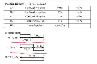
    I'm not that familiar with the WS2812 but I found some timing requirements from the document here: https://cdn-shop.adafruit.com/datasheets/WS2812.pdf. Are these correct for your device? If so, are you able to tell from the scope trace how much off you are for '1' and '0' with the default configuration?

    I think it might help to simply turn on the HFXO as it will improve the accuracy of the SPI clock. HFINT which is enabled by default have can have a drift of up to +- 6%.

    Best regards,

    Vidar

  • I was able to identify a solution by slightly modifying the driver code to accommodate my inverting driver. You'll notice in the .overlay file that comes with the sample code has the ONE_FRAME value defined as 0x70 and the ZERO_FRAME defined as 0x40 and a clock speed of 4MHz (each bit becomes 250ns). So the following is true for the non-inverting, standard driver:


    spi-zero-frame = 
    0x40 = 
    0100000 =
    250ns pulse ON & 1050ns pulse OFF
    
    spi-one-frame = 
    0x70 = 
    01110000 = 
    750ns pulse ON & 900ns pulse OFF
    
    Reset signal (0) of 8us.

    Now, to change this code for the inverting logic level shifter we can observe the following changes:

    spi-zero-frame = 
    0xBF = 
    10111111 =
    250ns pulse OFF & 1050ns pulse ON
    
    spi-one-frame = 
    0x8F = 
    10001111 = 
    750ns pulse OFF & 900ns pulse ON
    
    Reset signal (1) of 8us

    The reset signal becomes a little tricky in the inverting world. I was able to achieve this by filling a buffer length of 5 with 0xFF. This is because with our  clock frequency of 4MHz, 1 bit = 250us, so 5 * 8 bits * 250ns = 10us.

    By modifying the driver code slightly, we can replace the line:
    ws2812_reset_delay(); 

    (in zephyr/drivers/led_strip/ws2812_spi.c)

    with:

    // This is the reset line
    uint8_t res_buf[5];
    memset(&res_buf, 0xFF, sizeof(res_buf));
    struct spi_buf res_spi_buf = {
    	.buf = &res_buf,
    	.len = sizeof(res_buf),
    };
    const struct spi_buf_set res_tx = {
    	.buffers = &res_spi_buf,
    	.count = 1
    };
    rc = spi_write(dev_data(dev)->spi, &cfg->spi_cfg, &res_tx);

  • Thank you for posting the solution here! It looks like you found a good way to generate the reset signal. But are you sure 10 uS will be sufficient? I noticed it said >50uS in the datasheet I found.

  • The original `ws2812_reset_delay(); ` function call in the driver delayed for 8us. Since we've validated previous hardware revisions with the stock driver, I tried to recreate its functionality as close as possible. I'll keep an eye on it and know what to tweak if something doesn't look right. 

Related