This post is older than 2 years and might not be relevant anymore
More Info: Consider searching for newer posts

How to start pwm sequence after particular time delay of gpio event?

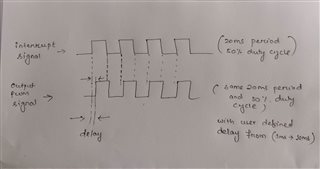
I am working on an application where I need to start pwm sequence after particular delay (accurate delay of multiple of 100us).

I am quite new to nordic environment.

Here is my code . Can please guide me what is wrong here??

#define    Period    20000 //20ms

const nrf_drv_timer_t TIMER_LED = NRF_DRV_TIMER_INSTANCE(0);

APP_PWM_INSTANCE(PWM1,1); 

static int gpio_flag =0;

void pwm_update(void)
{
      uint32_t value;
      value = duty_1;
      ready_flag = false;
      /* Set the duty cycle - keep trying until PWM is ready... */


      while ((app_pwm_channel_duty_set(&PWM1, 0, value))&(app_pwm_channel_duty_set(&PWM1, 1, value)) == NRF_ERROR_BUSY);
 
      /* ... or wait for callback. */
      while (!ready_flag);
      APP_ERROR_CHECK(app_pwm_channel_duty_set(&PWM1, 1, value));
      APP_ERROR_CHECK(app_pwm_channel_duty_set(&PWM1, 0, value));

}


void in_pin_handler(nrf_drv_gpiote_pin_t pin, nrf_gpiote_polarity_t action)
{
   gpio_flag =1;
   nrf_drv_timer_enable(&TIMER_LED);

   
}

void timer0_handler(nrf_timer_event_t event_type, void* p_context)
{
  switch (event_type)
    {
        case NRF_TIMER_EVENT_COMPARE0:
             timer_flg =1;
             nrf_drv_timer_clear(&TIMER_LED);
             gpio_flag=0;
             pwm_update();
            break;

        default:
            //Do nothing.
            break;
    }
}


void timer_init(void)
{
    uint32_t time_us = 500; 
    uint32_t time_ticks;
    uint32_t err_code = NRF_SUCCESS;

    nrf_drv_timer_config_t timer_cfg = NRF_DRV_TIMER_DEFAULT_CONFIG;
    err_code = nrf_drv_timer_init(&TIMER_LED, &timer_cfg, timer0_handler);
    APP_ERROR_CHECK(err_code);

    time_ticks = nrf_drv_timer_us_to_ticks(&TIMER_LED, time_us);
    nrf_drv_timer_compare(
         &TIMER_LED, NRF_TIMER_CC_CHANNEL0, time_ticks, true);

    
}

  • Hello again, Ram

    Attached you'll find an example that updates the PWM duty cycle using a button to start a timer that calls the pwm_update function when it expires. The delay is configurable and defined at the top of main.c
    To test the example just flash it to a nRF52 DK and press button 1 on the DK -  after the configurable delay has passed it will call the (currently empty) pwm_update function.

    I did not know exactly what you would like to update the PWM to, or what configuration you need to PWM to have wrt. frequency and polarity, so I used the default pwm configuration from the pwm_library example, and left the pwm_update function empty.
    You could also reconfigure the input to be a non-button pin, if that's what you are going to use in your application.

    Take a look and let me know if this was what you were looking for, or if you should have any questions! :) 

    Best regards,
    Karl

  • Strange, it seems something went wrong with the previous upload.
    I try again here:
    5852.pwm_button_timer_demo.zip

    I also forgot to mention: extract the .zip to your SDK17.0.2/examples/peripheral path.

  • Hello Karl,

    ake a look and let me know if this was what you were looking for, or if you should have any questions!

    I definitely tested this today and update you the status .

    Advance thank you for valuable time and inputs. 

    Thanks & regards,
    Ram

  • Great, I look forward to hearing if this was what you were looking for.

    RAM_MS said:
    Advance thank you for valuable time and inputs. 

    It is no problem at all, Ram - I am happy to help!

    Best regards,
    Karl

  • Hello Karl,

                   Thank you for your valuable inputs .

                   I tried with your code and timer is triggering but instead of 1ms delay its coming increments                         automatically.

                   For your better understand I am attaching both project .zip and my configuration aim in .png file

                  Also I am adding video of my outputs.

    pwm_library_timer_delay.zip

    The yellow signal is the interrupt signal and the blue signal is my pwm signal .

    Thanks & regards,
    Ram

Related