nRF52840 UARTE in Zephyr

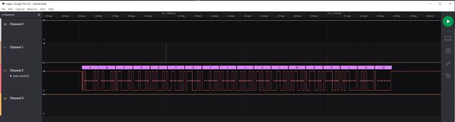
I'm having problems using the UARTE in the nRF52840 via Zephyr.    I'm watching the TX pin using a logic analyzer and seeing correct data when running at 9600 baud.   But if I configure the UART for 115200 baud, the data is garbled (sometimes some later characters are correct).   I've tried using the "built-in" Zephyr UART driver and disabling it and using the nrfxlib uarte driver with the same results.

I suspect that there is a clock accuracy issue...

I set:

CONFIG_CLOCK_CONTROL_NRF_K32SRC_RC=n
CONFIG_CLOCK_CONTROL_NRF_K32SRC_XTAL=y

in prj.conf since my board has a 32.768 KHz crystal.     Is there some other configuration option needed to use the UARTE at 115200 baud?

Thanks!

Parents
  • Hi,


    I'm watching the TX pin using a logic analyzer and seeing correct data when running at 9600 baud.   But if I configure the UART for 115200 baud, the data is garbled (sometimes some later characters are correct).   I've tried using the "built-in" Zephyr UART driver and disabling it and using the nrfxlib uarte driver with the same results.

    Your current configuration sets the LFCLK, while the UART's tolerance comes from the HFCLK.

    If you are running with the internal 64M RC oscillator, it is quite inaccurate (in the percent area). You can request the HFXO using this sequence:

    https://github.com/nrfconnect/sdk-nrf/blob/v1.7.0/samples/bluetooth/direct_test_mode/src/dtm.c#L497-L527


    Kind regards,

    Håkon

  • Hi,

    Thanks for your response.

    I tried using the clock_init() function you highlighted in the link you provided.     It did not solve the problem I am seeing (logic analyzer (using async analyzer/decoder) sees correct output sequence when UART is set to 9600 (via .dts file setting), but characters are wrong when the .dts file is changed to 115200).

    err is reported as 0 (I assume that means everything is OK).

    Would I be better off using the nrfx uarte driver from nrfxlib (versus the Zephyr built-in UART driver)?   Or are they the same?

    Is there anything else that could be happening here?

    I see in case ID 205318, a comment that turning on BLE might automatically switch the HFCLK to the internal oscillator to save power, and that a call to sd_clock_hfclk_request() is needed to ensure the HFCLK is kept with the crystal.   Is this also true when using BLE in Zephyr?   If so, is there an equivalent call in the Zephyr BLE API (the bt_ functions vs. the sd_ functions)?

    Thanks!

  • Hi,


    CktDesigner said:
    Would I be better off using the nrfx uarte driver from nrfxlib (versus the Zephyr built-in UART driver)?   Or are they the same?

    The zephyr built-in driver is built on nrfx, so they're quite similar in what's underneath.

    CktDesigner said:
    I see in case ID 205318, a comment that turning on BLE might automatically switch the HFCLK to the internal oscillator to save power, and that a call to sd_clock_hfclk_request() is needed to ensure the HFCLK is kept with the crystal.   Is this also true when using BLE in Zephyr?   If so, is there an equivalent call in the Zephyr BLE API (the bt_ functions vs. the sd_ functions)?

    If you are using the softdevice controller (default for all bluetooth samples in NCS), you should use this function call to request the HFCLK:

    https://github.com/nrfconnect/sdk-nrfxlib/blob/v1.7.0/mpsl/include/mpsl_clock.h#L136


    For all other subsystems in zephyr (including the zephyr bluetooth link layer), the former clock_control function will work.

    CktDesigner said:
    Is there anything else that could be happening here?

    Could you show an example of the expected vs. corrupted output? Are you using a nRF5 DK or a external uart bridge?


    Kind regards,

    Håkon 

  • I'm using a custom board with a Laird BL654PA module.  The Laird module includes the main crystal and I have a 32.768 KHz crystal on the board (since it states in the spec that BLE works better using the crystal).

    So if I use the clock_init() function you suggested, do I still need the mpsl_clock_hfclk_request() function to keep the HFCLK on (when using BLE)?   

    I also tried "not enabling" BLE (but using the clock_init() function you provided), thinking that perhaps BLE was somehow disabling the XO version of HFCLK, just to see if that made a difference, but got the same results.

    Here is the expected waveform from my test (just a sequence of characters) when:

    current-speed = <9600>;

    is in the board's .dts file

    Using the same code, but recompiling with:

    current-speed = <115200>;

    in the board's .dts file, I get this output:

    Note that the overall shape of the two waves is very similar.   The beginning (first character) of the 115200 baud version looks a bit corrupted, which then (I'm guessing) shifts all of the other characters out, causing framing errors or bad decoding.

    By zooming in appropriately and lining up the two waveforms, it appears that the 115200 baud version doesn't start properly.    Could this be a problem with the UART or the clock?   After the first couple of characters, the waves track each other pretty closely, but since everything gets shifted the decoding fails.   Here is the beginning of the two waves, zoomed and lined up:

    Still trying to figure out what is happening...

    Thanks!

  • Hi,


    As the waveform has jittering, the parser is parsing at the incorrect edge.

    Q1: is this scope taken from reset state?

    Q2: Do you see the same issue if you connect a receiver on the other end?


    Kind regards,

    Håkon

Reply Children
  • Hi Hakon,

    Yes, that is what I meant by shifting causing decoding issues...

    Q1 answer: Yes.  I start the logic analyzer capture, then start the code, capturing the entire sequence, then stop the logic analyzer and zoom into the UART transaction.   This is the first (only) transaction.   I substituted the normal control sequence that should be sent for a simple letter sequence to help see the results on the logic analyzer.

    Q2 answer: There is a receiver attached.  The UART is connected to a Sierra Wireless XA1110 GPS module.   The module is delivered preconfigured to run at 115200 baud, so communication must be at that speed to configure anything (including changing the baud rate).  The two connections (TX_UART and RX_UART) are point-to-point and shown in the following images.   They are both only about 35 mm in length.   (The rectangular pads near the center of the trace are for clip points to attach the logic analyzer.)  I thought that perhaps this was a "transmission line" issue, but if that was the case, I would expect all edges to be affected, not just the ones in the first couple of characters.   Here are highlights of the two nets:

    The Laird module is on the right side;  the XA1110 is at the bottom left.

    Thanks...

  • Hi,


    CktDesigner said:
    Q1 answer: Yes.  I start the logic analyzer capture, then start the code, capturing the entire sequence, then stop the logic analyzer and zoom into the UART transaction.   This is the first (only) transaction.   I substituted the normal control sequence that should be sent for a simple letter sequence to help see the results on the logic analyzer.

    Jitters during, and straight after reset is to be expected, as the line is undefined prior to the firmware setting it. You can add a pull-up resistor on the line if you'd like.

    CktDesigner said:
    Q2 answer: There is a receiver attached.  The UART is connected to a Sierra Wireless XA1110 GPS module.   The module is delivered preconfigured to run at 115200 baud, so communication must be at that speed to configure anything (including changing the baud rate).  The two connections (TX_UART and RX_UART) are point-to-point and shown in the following images.   They are both only about 35 mm in length.   (The rectangular pads near the center of the trace are for clip points to attach the logic analyzer.)  I thought that perhaps this was a "transmission line" issue, but if that was the case, I would expect all edges to be affected, not just the ones in the first couple of characters.   Here are highlights of the two nets:

    As you mention, if the issue is only in the startup sequence, the issue is not purely electrical in the sense that capacitance etc. is causing this. I believe it is related to the GPIO state when the nRF is in reset and starting up. Could you try to add a pull-up resistor on the line to see if this helps?


    Kind regards,

    Håkon

Related