
Hi,
I am trying to generate a 128Hz sine wave using the nrf_pwm library . First I tried this with SD110 enabled but ran into some problems that turned out to be a known issue with the nrf51 chip. So I tried generating my sine wave with the nrf_pwm library without softdevice but I still get the same problems. It does not occur as often but it still happens a few times every second. It seems the nrf_pwm timer changes counting direction randomly. The image below shows the sine wave after a RC filter.
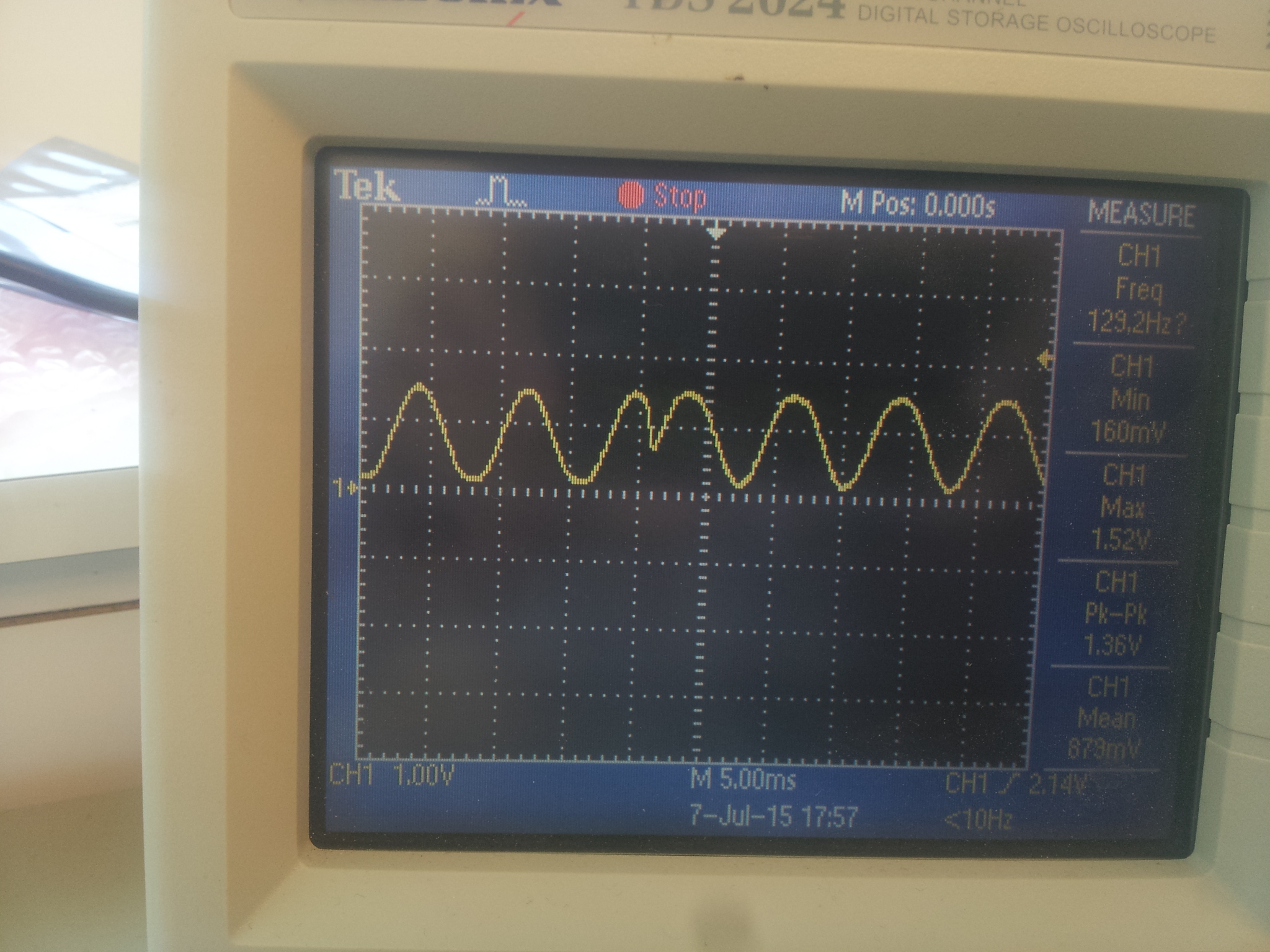
This error also seems to depend on timer settings, most timeouts gives this kind of error but with some timeout values I get a nice sine wave without "bumps", see line 6 in the initTimer function. Has anyone seen this before and managed to solve it? This is my code:
#include "DRV8662.h"
#include <components/drivers_nrf/hal/nrf_gpiote.h>
#include <components/drivers_nrf/hal/nrf51.h>
#include <components/softdevice/s110/headers/nrf_soc.h>
#include <components/drivers_nrf/hal/nrf51_bitfields.h>
#include <msp/drivers/board_ViTheSSG4rev1.h>
#include <msp/drivers/delay.h>

using namespace msp::peripherals;
using namespace msp::drivers;

namespace {
uint8_t phase = 0;

bool vibratorActive = false;

float attenuation = 1; // 1 is no attenuation, 0 is 100% atteunation

uint8_t channel = 0;

const uint8_t sine26[] = {0, 4, 16, 35, 59, 88, 120, 152, 182, 210, 232, 247,
    255, 255, 247, 232, 210, 182, 152, 120, 88, 59, 35, 16, 4, 0};
}

extern "C" {

void TIMER0_IRQHandler(void) {
  if (vibratorActive) {
    uint16_t amplitude = static_cast<float>(sine26[phase]) * attenuation;
    uint16_t offset = 128 - attenuation * 128;
    nrf_pwm_set_value(0, amplitude + offset);
    if (phase < 26) {
      phase += 1;
    } else {
      phase = 0;
    }
  }

  NRF_TIMER0->EVENTS_COMPARE[0] = 0;

  NRF_TIMER0->TASKS_CLEAR = 1; // Reset timer.
}

} // extern C

DRV8662::DRV8662(uint8_t enablePin, uint8_t pwmPin) :
    _enablePin(enablePin), _pwmPin(pwmPin), _vibrationLevel(0), _frequency(128), _phase(
        0), _channel(0), _maxLevel(5), _enabled(
    false) {

  pinOutput(_enablePin);
  pinOutput(_pwmPin);

  setVibrationLevel(_vibrationLevel);

  setFrequency(128);

  initPWM(_pwmPin, PWM_MODE_VITHESS_VIBRATOR);

  stop();
}

void DRV8662::initPWM(uint8_t pin, nrf_pwm_mode_t nrfPwmMode) {
  nrf_pwm_config_t
  pwm_config = PWM_DEFAULT_CONFIG;

  pwm_config.mode = nrfPwmMode;
  pwm_config.num_channels = 1;
  pwm_config.gpio_num[_channel] = pin;

  // Initialize the PWM library
  nrf_pwm_init (&pwm_config);

  // Start the external 16 MHz clock for a more accurate PWM frequency
  NRF_CLOCK->TASKS_HFCLKSTART = 1;

  nrf_pwm_set_value(_channel, 0); // start LOW

  // make available in extern C
  channel = _channel;
}

void DRV8662::initTimer(uint16_t frequency) {
  NRF_TIMER0->MODE = TIMER_MODE_MODE_Timer;  // Set the timer in Counter Mode
  NRF_TIMER0->TASKS_CLEAR = 1;  // clear the task first to be usable for later
  NRF_TIMER0->PRESCALER = 5; //Set prescaler. Higher number gives slower timer. Prescaler = X gives 16MHz/2^X Hz timer
  NRF_TIMER0->BITMODE = TIMER_BITMODE_BITMODE_16Bit; //Set counter to 16 bit resolution
  //NRF_TIMER0->CC[0] = 500000 / (frequency * 100); //Set value for timer compare register 0, timer period is 2us, pwm period is (1/(freq*255)), pwm period/timer period is 15
  NRF_TIMER0->CC[0] = 107; //most values causes strange artifacts... 98, 107, 118, 150 works TODO: investigate
  //NRF_TIMER0->CC[0] += us / 4;      // TODO: find out why we do this.

  // Enable interrupt on Timer 1,for CC[0]
  NRF_TIMER0->INTENSET = (TIMER_INTENSET_COMPARE0_Enabled
      << TIMER_INTENSET_COMPARE0_Pos);
//  sd_nvic_SetPriority(TIMER0_IRQn, 3);
//  sd_nvic_EnableIRQ(TIMER0_IRQn);

  NVIC_SetPriority(TIMER0_IRQn, 3);
  NVIC_EnableIRQ(TIMER0_IRQn);
}

uint8_t DRV8662::setVibrationLevel(uint8_t vibrationLevel) {
  // Set vibration level
  _vibrationLevel = vibrationLevel;

  switch (_vibrationLevel) {
  case 0:
    attenuation = 0;
    break;
  case 1:
    attenuation = 0.3;
    break;
  case 2:
    attenuation = 0.5;
    break;
  case 3:
    attenuation = 0.8;
    break;
  case 4:
    attenuation = 1;
    break;
  default:
    attenuation = 1;
    break;
  }

  return 0; // return 0 if params in range
}
uint8_t DRV8662::setFrequency(uint16_t frequency) {
  // Set frequency
  _frequency = frequency;
  initTimer(_frequency);

  return 0; // return 0 if params in range
}

void DRV8662::start() {
  // set pwm to 50%, transition enable from low to high, wait 2ms, datasheet 8.4.1.1
  nrf_pwm_set_value(_channel, 128);
  enable(true);
  delayMs(2);

  // Start timer
  NRF_TIMER0->TASKS_START = 1;               // Start timer.
  vibratorActive = true;
}

void DRV8662::stop() {
  // set pwm to 50% to bring differential output back to 0, datasheet 8.4.1.1
  nrf_pwm_set_value(_channel, 128);
  enable(false);
  delayMs(2);
  // stop timer
  NRF_TIMER0->TASKS_STOP = 1;
  vibratorActive = false;
  // shut down pwm TODO: find better way to do this
  nrf_pwm_set_value(0, 0);
}

uint8_t DRV8662::vibrationLevel() {
  return _vibrationLevel;
}

uint16_t DRV8662::frequency() {
  return _frequency;
}

uint8_t DRV8662::maxLevel() {
  return _maxLevel;
}

void DRV8662::enable(bool enabled) {
  if (enabled) {
    pinSet(_enablePin);
  } else {
    pinClear(_enablePin);
  }
  _enabled = enabled;
}

bool DRV8662::enabled() {
  return _enabled;
}

DRV8662::~DRV8662() {
// TODO: Write destructor
  NRF_TIMER0->TASKS_SHUTDOWN = 1; // Shut down timer.
}
