Hi!
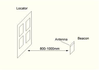
I developed a locator and beacon pcb boards for AoA direction finding using the NRF52811 chip. The locator has 4 patch antennas and the SKY13575-639LF external antenna switch.
Software configuration for the beacon (using infocenter.nordicsemi.com/.../intro.html) :
1. Radio:
/* Enable power to RADIO */
NRF_RADIO->POWER = 1;

/* Set radio transmit power to 0dBm */
NRF_RADIO->TXPOWER = (RADIO_TXPOWER_TXPOWER_0dBm << RADIO_TXPOWER_TXPOWER_Pos);

/* Set radio mode to 1Mbit/s Bluetooth Low Energy */
NRF_RADIO->MODE = (RADIO_MODE_MODE_Ble_1Mbit << RADIO_MODE_MODE_Pos);

/* Set the requested channel */
NRF_RADIO->FREQUENCY = GetChannelFrequency(channel);

/* This value needs to correspond to the channel being used */
NRF_RADIO->DATAWHITEIV = channel;

/* Configure Access Address according to the BLE standard */
NRF_RADIO->PREFIX0 = 0x8e;
NRF_RADIO->BASE0 = 0x89bed600;

/* Use logical address 0 (prefix0 + base0) = 0x8E89BED6 when transmitting and receiving */
NRF_RADIO->TXADDRESS = 0x00;
NRF_RADIO->RXADDRESSES = 0x01;

/* PCNF-> Packet Configuration.
* We now need to configure the sizes S0, S1 and length field to match the
* datapacket format of the advertisement packets.
*/
NRF_RADIO->PCNF0 = (
	(((1UL) << RADIO_PCNF0_S0LEN_Pos) & RADIO_PCNF0_S0LEN_Msk) |  /* Length of S0 field in bytes 0-1.    */
	(((0UL) << RADIO_PCNF0_S1LEN_Pos) & RADIO_PCNF0_S1LEN_Msk) |  /* Length of S1 field in bits 0-8.     */
	(((8UL) << RADIO_PCNF0_LFLEN_Pos) & RADIO_PCNF0_LFLEN_Msk)    /* Length of length field in bits 0-8. */
);

/* Packet configuration */
NRF_RADIO->PCNF1 = (
	(((64UL) << RADIO_PCNF1_MAXLEN_Pos) & RADIO_PCNF1_MAXLEN_Msk)   |                      /* Maximum length of payload in bytes [0-255] */
	(((0UL) << RADIO_PCNF1_STATLEN_Pos) & RADIO_PCNF1_STATLEN_Msk)   |                      /* Expand the payload with N bytes in addition to LENGTH [0-255] */
	(((3UL) << RADIO_PCNF1_BALEN_Pos) & RADIO_PCNF1_BALEN_Msk)       |                      /* Base address length in number of bytes. */
	(((RADIO_PCNF1_ENDIAN_Little) << RADIO_PCNF1_ENDIAN_Pos) & RADIO_PCNF1_ENDIAN_Msk) |  /* Endianess of the S0, LENGTH, S1 and PAYLOAD fields. */
	(((1UL) << RADIO_PCNF1_WHITEEN_Pos) & RADIO_PCNF1_WHITEEN_Msk)                         /* Enable packet whitening */
);

/* CRC config */
NRF_RADIO->CRCCNF  = (RADIO_CRCCNF_LEN_Three << RADIO_CRCCNF_LEN_Pos) |
					 (RADIO_CRCCNF_SKIPADDR_Skip << RADIO_CRCCNF_SKIPADDR_Pos); /* Skip Address when computing CRC */
NRF_RADIO->CRCINIT = 0x555555;                                                  /* Initial value of CRC */
NRF_RADIO->CRCPOLY = 0x00065B;                                                  /* CRC polynomial function */

/* Clear events */
NRF_RADIO->EVENTS_DISABLED = 0;
NRF_RADIO->EVENTS_END = 0;
NRF_RADIO->EVENTS_READY = 0;
NRF_RADIO->EVENTS_ADDRESS = 0;
//-------------------------------------
//-------------------------------------
NRF_RADIO->PACKETPTR = (uint32_t) Packet;

// Set up AoA mode
NRF_RADIO->DFEMODE = RADIO_DFEMODE_DFEOPMODE_AoA;

NRF_RADIO->DFECTRL1 = 3 << RADIO_DFECTRL1_NUMBEROF8US_Pos | 1 << RADIO_DFECTRL1_DFEINEXTENSION_Pos;
2. Sending a packet:
NRF_RADIO->EVENTS_READY = 0U;
// Enable radio and wait for ready.
NRF_RADIO->TASKS_TXEN   = 1;
while (NRF_RADIO->EVENTS_READY == 0U){}

NRF_RADIO->TASKS_START = 1U;
// Start transmission.
NRF_RADIO->EVENTS_PHYEND = 0;

NRF_RADIO->EVENTS_END  = 0U;


// Wait for end of the transmission packet.

while (NRF_RADIO->EVENTS_PHYEND == 0U)
{
    while (NRF_RADIO->EVENTS_END == 0U)
    {
		//counter1++;
    }
    counter2++;
}

NRF_RADIO->EVENTS_DISABLED = 0U;
// Disable the radio.
NRF_RADIO->TASKS_DISABLE   = 1U;
while (NRF_RADIO->EVENTS_DISABLED == 0U){}
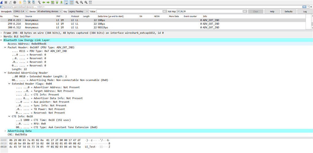
3. The resulting structure of the packet:

Software configuration for the locator (using infocenter.nordicsemi.com/.../intro.html):
1. Radio:
/* Enable power to RADIO */
NRF_RADIO->POWER = 1;

/* Set radio transmit power to 0dBm */
NRF_RADIO->TXPOWER = (RADIO_TXPOWER_TXPOWER_0dBm << RADIO_TXPOWER_TXPOWER_Pos);

/* Set radio mode to 1Mbit/s Bluetooth Low Energy */
NRF_RADIO->MODE = (RADIO_MODE_MODE_Ble_1Mbit << RADIO_MODE_MODE_Pos);

/* Set the requested channel */
NRF_RADIO->FREQUENCY = GetChannelFrequency(channel);

/* This value needs to correspond to the channel being used */
NRF_RADIO->DATAWHITEIV = channel;

/* Configure Access Address according to the BLE standard */
NRF_RADIO->PREFIX0 = 0x8e;
NRF_RADIO->BASE0 = 0x89bed600;

/* Use logical address 0 (prefix0 + base0) = 0x8E89BED6 when transmitting and receiving */
NRF_RADIO->TXADDRESS = 0x00;
NRF_RADIO->RXADDRESSES = 0x01;

/* PCNF-> Packet Configuration.
* We now need to configure the sizes S0, S1 and length field to match the
* datapacket format of the advertisement packets.
*/
NRF_RADIO->PCNF0 = (
	(((1UL) << RADIO_PCNF0_S0LEN_Pos) & RADIO_PCNF0_S0LEN_Msk) |  /* Length of S0 field in bytes 0-1.    */
	(((0UL) << RADIO_PCNF0_S1LEN_Pos) & RADIO_PCNF0_S1LEN_Msk) |  /* Length of S1 field in bits 0-8.     */
	(((8UL) << RADIO_PCNF0_LFLEN_Pos) & RADIO_PCNF0_LFLEN_Msk)    /* Length of length field in bits 0-8. */
);

/* Packet configuration */
NRF_RADIO->PCNF1 = (
	(((64UL) << RADIO_PCNF1_MAXLEN_Pos) & RADIO_PCNF1_MAXLEN_Msk)   |                      /* Maximum length of payload in bytes [0-255] */
	(((0UL) << RADIO_PCNF1_STATLEN_Pos) & RADIO_PCNF1_STATLEN_Msk)   |                      /* Expand the payload with N bytes in addition to LENGTH [0-255] */
	(((3UL) << RADIO_PCNF1_BALEN_Pos) & RADIO_PCNF1_BALEN_Msk)       |                      /* Base address length in number of bytes. */
	(((RADIO_PCNF1_ENDIAN_Little) << RADIO_PCNF1_ENDIAN_Pos) & RADIO_PCNF1_ENDIAN_Msk) |  /* Endianess of the S0, LENGTH, S1 and PAYLOAD fields. */
	(((1UL) << RADIO_PCNF1_WHITEEN_Pos) & RADIO_PCNF1_WHITEEN_Msk)                         /* Enable packet whitening */
);

/* CRC config */
NRF_RADIO->CRCCNF  = (RADIO_CRCCNF_LEN_Three << RADIO_CRCCNF_LEN_Pos) |
					 (RADIO_CRCCNF_SKIPADDR_Skip << RADIO_CRCCNF_SKIPADDR_Pos); /* Skip Address when computing CRC */
NRF_RADIO->CRCINIT = 0x555555;                                                  /* Initial value of CRC */
NRF_RADIO->CRCPOLY = 0x00065B;                                                  /* CRC polynomial function */

/* Clear events */
NRF_RADIO->EVENTS_DISABLED = 0;
NRF_RADIO->EVENTS_END = 0;
NRF_RADIO->EVENTS_READY = 0;
NRF_RADIO->EVENTS_ADDRESS = 0;
//-------------------------------------
//-------------------------------------
NRF_RADIO->PACKETPTR = (uint32_t) Packet;

// Set up AoA receiver mode
NRF_RADIO->DFEMODE |= RADIO_DFEMODE_DFEOPMODE_AoA;

NRF_RADIO->DFECTRL1 = 3 << RADIO_DFECTRL1_NUMBEROF8US_Pos | 1 << RADIO_DFECTRL1_DFEINEXTENSION_Pos;

NRF_RADIO->CTEINLINECONF |= (RADIO_CTEINLINECONF_CTEINLINECTRLEN_Enabled << RADIO_CTEINLINECONF_CTEINLINECTRLEN_Pos)
						 | (RADIO_CTEINLINECONF_CTEINFOINS1_NotInS1 << RADIO_CTEINLINECONF_CTEINFOINS1_Pos)
						 | (0x07 << RADIO_CTEINLINECONF_S0CONF_Pos)
						 | (0x0F << RADIO_CTEINLINECONF_S0MASK_Pos);
2. Antenna switching:
#define ANTENNA_SWICTH_PIN0 30
#define ANTENNA_SWICTH_PIN1 28

// Configure antenna switching every 2 µs
NRF_RADIO->DFECTRL1 |= RADIO_DFECTRL1_TSWITCHSPACING_2us << RADIO_DFECTRL1_TSWITCHSPACING_Pos;

// Antenna 1 (for data)
NRF_RADIO->SWITCHPATTERN = 0b00;
// Antenna 1 (guard/reference)
NRF_RADIO->SWITCHPATTERN = 0b00;
// Antenna 2 (guard/reference)
NRF_RADIO->SWITCHPATTERN = 0b01;
// Antenna 3 (guard/reference)
NRF_RADIO->SWITCHPATTERN = 0b10;
// Antenna 4 (guard/reference)
NRF_RADIO->SWITCHPATTERN = 0b11;


// Set up the first switching pin
NRF_RADIO->PSEL.DFEGPIO[0] = ANTENNA_SWICTH_PIN0;
// Set up the second switching pin
NRF_RADIO->PSEL.DFEGPIO[0] = ANTENNA_SWICTH_PIN1;

// Set the switch offset to zero
NRF_RADIO->DFECTRL2 |= (0 << RADIO_DFECTRL2_TSWITCHOFFSET_Pos);

// Config antenna swithcing pins as output
nrf_gpio_cfg_output(ANTENNA_SWICTH_PIN0);
nrf_gpio_cfg_output(ANTENNA_SWICTH_PIN1);
nrf_gpio_pin_write(ANTENNA_SWICTH_PIN0, 0);
nrf_gpio_pin_write(ANTENNA_SWICTH_PIN0, 0);
3. IQ samples receiving:
struct IQ_Sample
{
    int16_t I;
    int16_t Q;
};

static IQ_Sample DFE_Packet[64] = {0};


// Set the sample type to IQ format
NRF_RADIO->DFECTRL1 |= (0 << RADIO_DFECTRL1_SAMPLETYPE_Pos);
// Configure the DMA pointer to RAM
NRF_RADIO->DFEPACKET.PTR = (uint32_t) DFE_Packet;
// Configure the size of the reserved buffer
NRF_RADIO->DFEPACKET.MAXCNT = 0x1C;
// Set the sample spacing to 1 µs for the reference period
NRF_RADIO->DFECTRL1 |= (RADIO_DFECTRL1_TSAMPLESPACINGREF_1us << RADIO_DFECTRL1_TSAMPLESPACINGREF_Pos);
// Set sample offset to 1
NRF_RADIO->DFECTRL2 |= (3 << RADIO_DFECTRL2_TSAMPLEOFFSET_Pos);
// Set sample spacing to 2 µs for the sample slots with Constant Tone Extension (CTE) inline mode
NRF_RADIO->CTEINLINECONF |= (RADIO_CTEINLINECONF_CTEINLINERXMODE2US_2us << RADIO_CTEINLINECONF_CTEINLINERXMODE1US_Pos);
4. Waiting for the packet:
NRF_RADIO->EVENTS_READY = 0U;
// Enable radio and wait for ready
NRF_RADIO->TASKS_RXEN = 1U;

while (NRF_RADIO->EVENTS_READY == 0U)
{
    // wait
}
NRF_RADIO->EVENTS_END = 0U;
// Start listening and wait for address received event
NRF_RADIO->TASKS_START = 1U;

// Wait for end of packet or buttons state changed
while (NRF_RADIO->EVENTS_END == 0U)
{
    // wait
}

if (NRF_RADIO->CRCSTATUS == 1U)
{
    result = 0;
}
NRF_RADIO->EVENTS_DISABLED = 0U;
// Disable radio
NRF_RADIO->TASKS_DISABLE = 1U;

while (NRF_RADIO->EVENTS_DISABLED == 0U)
{
    // wait
}
5. Handling the packet:
if (NRF_RADIO->EVENTS_CTEPRESENT)
{
    NRF_RADIO->EVENTS_CTEPRESENT = 0;

    for (uint8_t i = 0; i < 4; i++)
    {
        UART_Instance.Printf("I and Q;");
        UART_Instance.Printf("%d;%d;\r\n", DFE_Packet[i].I, DFE_Packet[i].Q);
    }
}
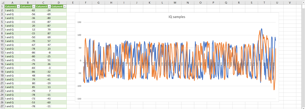
Why the resulting IQ samples look like random values?


