Thank you ahead of time for any help that the community can provide. These forums have taught me a lot over the past few weeks.
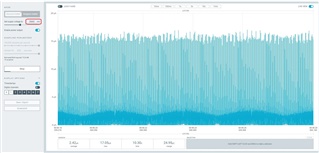
In my project, I am noticing 20x higher sleep mode current draw when using nrfx_clock interfaces (60uA idle) versus using nrf_drv_clock (3uA idle) to drive app_timer.
- Issue is reproducible on both nRF52DK and on custom board with nRF52832.
- Taking current consumption measurements via Power Profiler II in source meter mode.
- Actual project includes use of power management, ESB, GPIOs, ADC, most RAM off.
- No soft devices in use
- Project built with VSCode/GCC.
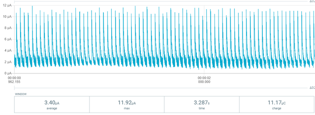
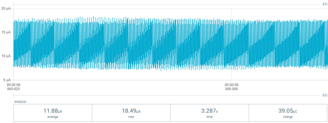
I can reproduce the issue with a bare-bones project, although the difference is smaller, as shown in the captures below.
Idle consumption using nrf_drv_clock
Idle consumption using nrfx_clock
Here is a bare-bones project that can easily demonstrate the difference, by changing a single line.
Source code
// TODO - change below to switch between legacy/nrfx interfaces.#define USE_NRFX_IF#include "sdk_config.h"#include "app_timer.h"#ifdef USE_NRFX_IF#include "nrfx_clock.h"static void nrfxClockIrqHandler(nrfx_clock_evt_type_t evt){}#else#include "nrf_drv_clock.h"#endifint main(void){#ifdef USE_NRFX_IF (void)nrfx_clock_init(nrfxClockIrqHandler); nrfx_clock_lfclk_start();#else (void)nrf_drv_clock_init(); nrf_drv_clock_lfclk_request(NULL);#endif app_timer_init(); while (true) { __WFE(); }}SDK Config
#ifndef SDK_CONFIG_H#define SDK_CONFIG_H#define NRF_LOG_ENABLED 0#define APP_TIMER_ENABLED 1#define APP_TIMER_CONFIG_RTC_FREQUENCY 0#define APP_TIMER_CONFIG_IRQ_PRIORITY 6#define APP_TIMER_CONFIG_OP_QUEUE_SIZE 10#define APP_TIMER_CONFIG_USE_SCHEDULER 0#define APP_TIMER_KEEPS_RTC_ACTIVE 1#define APP_TIMER_SAFE_WINDOW_MS 300000#define APP_TIMER_WITH_PROFILER 0#define APP_TIMER_CONFIG_SWI_NUMBER 1#ifdef USE_NRFX_IF#define NRFX_CLOCK_ENABLED 1#define NRFX_CLOCK_CONFIG_LF_SRC 1#define NRFX_CLOCK_CONFIG_IRQ_PRIORITY 6#define NRFX_CLOCK_CONFIG_LOG_ENABLED 0#else#define NRF_CLOCK_ENABLED 1#define CLOCK_CONFIG_LF_SRC 1#define CLOCK_CONFIG_LF_CAL_ENABLED 0#define CLOCK_CONFIG_IRQ_PRIORITY 6#endif#endif //SDK_CONFIG_HMakefile
SRC_FILES += \ $(PROJ_DIR)/main.c \ $(SDK_ROOT)/components/libraries/timer/app_timer.c \ $(SDK_ROOT)/components/libraries/util/app_util_platform.c \ $(SDK_ROOT)/modules/nrfx/drivers/src/nrfx_clock.c \ $(SDK_ROOT)/integration/nrfx/legacy/nrf_drv_clock.c \ $(SDK_ROOT)/components/boards/boards.c \ $(SDK_ROOT)/modules/nrfx/mdk/gcc_startup_nrf52.S \ $(SDK_ROOT)/modules/nrfx/mdk/system_nrf52.c \Please let me know if anyone can spot something I may be missing that is causing this discrepancy.
Thank you
-a
Thank you
-a