Thingy91 accessing P6 GPIO of nrf52840

Hello,

 I am trying to work on a simple GPIO program for the Thingy:91 which involves reading a pin for sensor inputs (this will be 2 sensors eventually). I have tried to look through the documentation in the infocenter and I believe that the way to do this would be to use the P6 spare GPIO of the nrf52480 (Nordic Semiconductor Infocenter table 4 pinout of connector P6).

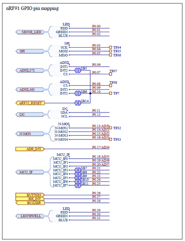
My question is how to access these GPIO pins and set them as inputs/read from them, as I assumed that to reference P6.1 I would use the provided NRF_GPIO_PIN_MAP macro to reference Port 6, pin 1. This however seems to enable the green color of color sensor support LED, which is P0.1. 

Could someone point me in the right direction/ explain how to access these P6 GPIO pins?

I've included the small code snippet as further info. 

Thanks!

-Julian

#include <zephyr.h>
#include <sys/printk.h>
#include <hal/nrf_gpio.h>
#define INPUT NRF_GPIO_PIN_MAP(6, 1)

void main(void)
{
	printk("Hello World! %s\n", CONFIG_BOARD);
	nrf_gpio_cfg_output(29);
	nrf_gpio_pin_write(29, 1); // sets red RGB LED high as expected

	nrf_gpio_cfg_output(13);
	nrf_gpio_pin_write(13, 1); // sets Test Point 32 high as expected

	nrf_gpio_cfg_output(INPUT);
	nrf_gpio_pin_write(INPUT, 1); // sets green color of color sensor support LED high? unexpected
}

Parents
  • Hello Julian,

    If you would like to use the pins on P6 you would need to program nRF52840 with a modified version of the Connectivity Bridge firmware. Remember to set the switch to nRF52 on the Thingy when programming the 52 device.

    Why did you see a green light?

    NRF_GPIO_PIN_MAP is provided to reference the ports and pins on the IC, not the ports and pins on Thingy:91. Which LED goes green, the SENSE_LED or the lightwell?

    If it is the SENSE_LED that goes green then I suppose the explanation could be that this result after the use of the macro is port 0, pin 1(P0.01) on nRF9160.

    Other solutions
    (this will be 2 sensors eventually)

    How many pins/what type of pins are required for the two sensors?

    Here are a few more options for GPIOs on Thingy:91: https://devzone.nordicsemi.com/f/nordic-q-a/51355/inputs-via-gpio-on-the-thingy-91

    Another discussion on alternative use of the pins on Thingy:91: https://devzone.nordicsemi.com/f/nordic-q-a/68213/thingy91-uart-external-communication/279485#279485

    It looks like SPI is available on some test points.

    Best regards,

    Håkon

  • Hi, thanks for telling us about the modified Connectivity Bridge firmware need, could you explain further what exactly has to be modified, as the CONFIG_GPIO is already set to y and I can't see anything else that would be relevant?

    Yes it was the SENSE_LED - the Port 0 Pin 1 explanation seems right to me.

    One of the sensors needs power/GND/Analog input, while the other sensor just needs power/Analog input. The power and GND connections will be done with connector P5 (the 3.3V and GND connections).

    Really all I need to do is read the analog voltage on two of the 6 pins on P6 or the test points 32 and 33. I am able to read the logical level on the test points, however I really need the actual voltage on the point. Is there a way to get the actual voltage level from pin reads?

    Those two tickets you linked were helpful, thanks!

Reply
  • Hi, thanks for telling us about the modified Connectivity Bridge firmware need, could you explain further what exactly has to be modified, as the CONFIG_GPIO is already set to y and I can't see anything else that would be relevant?

    Yes it was the SENSE_LED - the Port 0 Pin 1 explanation seems right to me.

    One of the sensors needs power/GND/Analog input, while the other sensor just needs power/Analog input. The power and GND connections will be done with connector P5 (the 3.3V and GND connections).

    Really all I need to do is read the analog voltage on two of the 6 pins on P6 or the test points 32 and 33. I am able to read the logical level on the test points, however I really need the actual voltage on the point. Is there a way to get the actual voltage level from pin reads?

    Those two tickets you linked were helpful, thanks!

Children
No Data
Related