

Sorry, I have accidentally closed my previous question, so I repost it again.
Hello,
I´m working on my audio project and I try to stream some audio data (currently a 1 kHz square wave signal with 3.3 V peak) over I2S. The audio signal is sampled by an ADC in the free-running mode.
#include "app_error.h"
#include "nrf_drv_ppi.h"
#include "nrf_drv_i2s.h"
#include "nrf_drv_saadc.h"
#include "nrf_drv_timer.h"
#include "nrf_gpio.h"

#include "nrf_log.h"
#include "nrf_log_ctrl.h"
#include "nrf_log_default_backends.h"

#define LED_0			17
#define BUTTON_0		13
#define BUTTON_1		14
#define TRIGGER			31
#define SAMPLES			128

static bool			IsStarted		= false;
static volatile uint32_t*	I2S_BlockToFill		= NULL;
static volatile uint32_t*	ADC_BlockToFill		= NULL;

static uint32_t			I2S_Buffer[2][SAMPLES];
static nrf_saadc_value_t	ADC_Buffer[2][SAMPLES];
static nrf_ppi_channel_t	PPI_Channel;

static const nrf_drv_timer_t	Timer = NRF_DRV_TIMER_INSTANCE(0);

void on_Timer_Handler(nrf_timer_event_t EventType, void* p_Context)
{
}

void on_SAADC_Handler(nrf_drv_saadc_evt_t const* p_Event)
{
    if(p_Event->type == NRF_DRV_SAADC_EVT_DONE)
    {
        APP_ERROR_CHECK(nrf_drv_saadc_buffer_convert(p_Event->data.done.p_buffer, SAMPLES));

	ADC_BlockToFill = (uint32_t*)p_Event->data.done.p_buffer;
    }
}

static void DataHandler(nrf_drv_i2s_buffers_t const* p_Released, uint32_t Status)
{
    // 'nrf_drv_i2s_next_buffers_set' is called directly from the handler
    // each time next buffers are requested, so data corruption is not
    // expected.
    ASSERT(p_Released);

    // When the handler is called after the transfer has been stopped
    // (no next buffers are needed, only the used buffers are to be
    // released), there is nothing to do.
    if(!(Status & NRFX_I2S_STATUS_NEXT_BUFFERS_NEEDED))
    {
        return;
    }

    // First call of this handler occurs right after the transfer is started.
    // No data has been transferred yet at this point, so there is nothing to
    // check. Only the buffers for the next part of the transfer should be
    // provided.
    if(!p_Released->p_tx_buffer)
    {
        nrf_drv_i2s_buffers_t const NextBuffer = {
            .p_tx_buffer = I2S_Buffer[1],
	    .p_rx_buffer = NULL,
        };

        APP_ERROR_CHECK(nrf_drv_i2s_next_buffers_set(&NextBuffer));

	nrf_gpio_pin_clear(TRIGGER);

        I2S_BlockToFill = I2S_Buffer[1];
    }
    else
    {
        // The driver has just finished accessing the buffers pointed by
        // 'p_Released'. They can be used for the next part of the transfer
        // that will be scheduled now.
        APP_ERROR_CHECK(nrf_drv_i2s_next_buffers_set(p_Released));

        // The pointer needs to be typecasted here, so that it is possible to
        // modify the content it is pointing to (it is marked in the structure
        // as pointing to constant data because the driver is not supposed to
        // modify the provided data).
        I2S_BlockToFill = (uint32_t*)p_Released->p_tx_buffer;
    }
}

void SAADC_Init(void)
{
    APP_ERROR_CHECK(nrf_drv_saadc_init(NULL, on_SAADC_Handler));
    APP_ERROR_CHECK(nrf_drv_ppi_init());

    nrf_drv_timer_config_t timer_cfg = NRF_DRV_TIMER_DEFAULT_CONFIG;
    timer_cfg.bit_width = NRF_TIMER_BIT_WIDTH_32;

    APP_ERROR_CHECK(nrf_drv_timer_init(&Timer, &timer_cfg, on_Timer_Handler));
    nrf_drv_timer_extended_compare(&Timer, NRF_TIMER_CC_CHANNEL0, nrf_drv_timer_us_to_ticks(&Timer, 23), NRF_TIMER_SHORT_COMPARE0_CLEAR_MASK, false);
    nrf_drv_timer_enable(&Timer);

    APP_ERROR_CHECK(nrf_drv_ppi_channel_alloc(&PPI_Channel));
    APP_ERROR_CHECK(nrf_drv_ppi_channel_assign(PPI_Channel, nrf_drv_timer_compare_event_address_get(&Timer, NRF_TIMER_CC_CHANNEL0), nrf_drv_saadc_sample_task_get()));

    nrf_saadc_channel_config_t Channel0 = NRF_DRV_SAADC_DEFAULT_CHANNEL_CONFIG_SE(NRF_SAADC_INPUT_AIN1);
    Channel0.acq_time = NRF_SAADC_ACQTIME_10US;

    APP_ERROR_CHECK(nrf_drv_saadc_channel_init(0, &Channel0));
    APP_ERROR_CHECK(nrf_drv_saadc_buffer_convert(ADC_Buffer[0], SAMPLES));
    APP_ERROR_CHECK(nrf_drv_saadc_buffer_convert(ADC_Buffer[1], SAMPLES));
    APP_ERROR_CHECK(nrf_drv_ppi_channel_enable(PPI_Channel));
}

int main(void)
{
    APP_ERROR_CHECK(NRF_LOG_INIT(NULL));
    NRF_LOG_DEFAULT_BACKENDS_INIT();

    SAADC_Init();

    nrf_gpio_cfg_input(BUTTON_0, NRF_GPIO_PIN_PULLUP);
    nrf_gpio_cfg_input(BUTTON_1, NRF_GPIO_PIN_PULLUP);

    nrf_gpio_cfg_output(TRIGGER);
    nrf_gpio_cfg_output(LED_0);
    nrf_gpio_pin_clear(TRIGGER);
    nrf_gpio_pin_set(LED_0);

    nrf_drv_i2s_config_t I2S_Config = NRF_DRV_I2S_DEFAULT_CONFIG;
    I2S_Config.sdin_pin	    = NRFX_I2S_PIN_NOT_USED;
    I2S_Config.sdout_pin    = 27;
    I2S_Config.lrck_pin	    = 26;
    I2S_Config.sck_pin	    = 25;
    I2S_Config.mck_pin	    = 2;
    I2S_Config.mck_setup    = NRF_I2S_MCK_32MDIV8;
    I2S_Config.ratio	    = NRF_I2S_RATIO_96X;
    I2S_Config.channels	    = NRF_I2S_CHANNELS_STEREO;
    APP_ERROR_CHECK(nrf_drv_i2s_init(&I2S_Config, DataHandler));

    nrf_drv_i2s_buffers_t const InitialBuffer = {
	.p_tx_buffer = I2S_Buffer[0],
        .p_rx_buffer = NULL,
    };

    while(1)
    {
	if(nrf_gpio_pin_read(BUTTON_0) == false)
	{
	    if(IsStarted == false)
	    {
		APP_ERROR_CHECK(nrf_drv_i2s_start(&InitialBuffer, SAMPLES, 0));
		NRF_LOG_INFO("I2S sender started...");
		IsStarted = true;
		nrf_gpio_pin_set(TRIGGER);
		nrf_gpio_pin_clear(LED_0);
	    }
	}
	else if(nrf_gpio_pin_read(BUTTON_1) == false)
	{
	    if(IsStarted)
	    {
		nrf_drv_i2s_stop();
		NRF_LOG_INFO("I2S sender stopped...");
		IsStarted = false;
		nrf_gpio_pin_clear(TRIGGER);
		nrf_gpio_pin_set(LED_0);
	    }
	}

	if(I2S_BlockToFill && ADC_BlockToFill)
        {
	    for(uint32_t i = 0x00; i < SAMPLES; i++)
	    {
		//int16_t Sample = (int16_t)(32768 * sin(2.0 * 3.14 * (double)i / ((double)SAMPLES)));
		I2S_BlockToFill[i] = (uint32_t)(0x0000 | (ADC_BlockToFill[i] & 0xFFFF));
	    }

            I2S_BlockToFill = NULL;
	    ADC_BlockToFill = NULL;
        }

	if(NRF_LOG_PROCESS())
	{
	    NRF_LOG_FLUSH();
	}
    }
}
The code from above will give a pretty poor signal when I use the ADC.
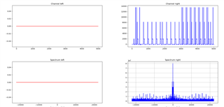
I have tried to figure out the reason for this and replaced the line
I2S_BlockToFill[i] = (uint32_t)(0x0000 | (ADC_BlockToFill[i] & 0xFFFF));
with
I2S_BlockToFill[i] = (uint32_t)(0x0000 | (i & 0xFFFF));
to produce data from a ramp signal and the signal looks much better.
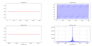
So it looks like the problem is based on the ADC. I have tried to use two buffers to use the same swapping buffer system as in the I2S example.
How can I improve this result?
@Karl:
I have changed the sdkconfig according to your suggestions from the last thread. I have removed the legacy stuff (except the PPI and UART stuff, because otherwise, the code doesn´t compile) and changed the SAADC back from LP to normal power mode and the result looks better.
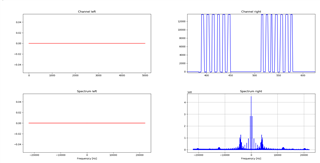
But there are some "holes" in the signal. I think there are some issues with the buffering.
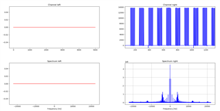
Edit:
I have visualized the transmission with my ILA. The gap and the transmissions have the same length.

So there is a transmission gap for sure.
