

Hi, I have this weird issue with the USB behaviour of some of our pre-production units.
2 boards with USB came out of the oven and their USB was working fine. I was able to program them with jtag and the usb cdc bootloader at the factory.
Next day one of the boards is giving us a device descriptor request fail error in windows while the other works fine.
I tried with another PC, change cables, reflashed the unit, etc. but the one pcb still has the same issue. The other PCB works well on all machines with all cables.
Ok that must be a hardware issue right? Maybe some dry solder joint.
Before doing any rework, I loaded a simple program that enables the USB peripheral and toggles the D+/- lines like this on the pcb that was not enumerating.
HAL_USB_SERIAL_begin();
while(1){
        nrf_usbd_dpdmvalue_set(2);
        nrf_usbd_task_trigger(NRF_USBD_TASK_DRIVEDPDM);
        HAL_CORE_delay(1);
        nrf_usbd_dpdmvalue_set(4);
        nrf_usbd_task_trigger(NRF_USBD_TASK_DRIVEDPDM);
        HAL_CORE_delay(1);
}
The toggling is seen (img below) on the scope once 5V is provided to the board that enables the USB peripheral. So the D+/- pins are connected to the USB connector!
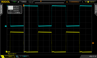
On both PCBs the USB signal integrity looks ok.
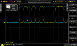
On the data side, I can notice the PCB that has the issue is not replying to the get descriptor request.

On the PCB that works, there is a PID ACK present.

Added/removed 39Ohm series resistors too, but no change.
Code wise, the issue exists even when loading the stock CDC USB bootloader.
Chip revision on the board is QIAA-D0x
Is there anything else that can affect the USB block behaviour?
Any thoughts on what I should try next? Thanks!

