Good evening, (I have a few questions which are at the bottom, so I hope you don't mind me having posted the full length of these two programs first)
I've managed to produce some great results in developing PPM (pulse position modulation; related to PWM pulse width modulation) for a head tracker project I'm working on. I've included two fundamentally different programs as described below, which I'm testing using my Nano 33 BLE via the Arduino development environment...
Method 1: Servo PPM using 2 timers (4 channels)
This method produces the best results (although method 2 does indeed work quite well). The servos move virtually perfectly smooth almost 100% of the time. Timer 3 CC[0] sets the initial high value of the waveform, followed by CC[1] to [4] for the 4 channels. CC[5] is used for the PPM frame length which is set to 22500 microseconds. Each timer 3 compare activates timer 4 which in turn controls the pulse length.
The GPIOTE tasks are controlled by timer events via PPI channels. One complete frame length is processed by timer 3 independent of timer 3 IRQ handler. After the frame is complete, timer 3 stops and clears, then the new servo values are transferred, and the timer is started again. The delay until the next frame starts is dependent on timer 3 prescaler which is set to 1MHz, which could be increased, and the PPM channel values scaled accordingly.
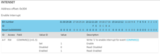
Note: I've omitted all Timer "_Pos" instructions except for TIMER_INTENSET (for GPIOTE I decided to just leave them all in place). _Pos is required for INTENSET even though it has only one field in its register (note "Write 1 to enable..." in the description. Without _Pos it doesn't work). Although SHORTS has 2 fields in its register, it doesn't need _Pos because I'm using its 1st field.
#include <nrf.h>

#define PPI_CHANNEL_0 (0)
#define PPI_CHANNEL_1 (1)
#define PPI_CHANNEL_2 (2)
#define PPI_CHANNEL_3 (3)
#define PPI_CHANNEL_4 (4)
#define PPI_CHANNEL_5 (5)

// #define PIN_GPIO (16) // Green for Nano 33 BLE
#define PIN_GPIO (2)
#define PORT (1)

/* Using timer 1 via MBED doesn't work, so perhaps it's being used */

void setup()
{
	// Configure PIN_GPIO as output
	// ----------------------------
	NRF_GPIO->DIRSET = (1UL << PIN_GPIO);

	// Configure GPIOTE
	// ----------------
	NRF_GPIOTE->CONFIG[0] =

	(GPIOTE_CONFIG_MODE_Task    << GPIOTE_CONFIG_MODE_Pos) |
	(PORT                	    << GPIOTE_CONFIG_PORT_Pos) |
	(PIN_GPIO                   << GPIOTE_CONFIG_PSEL_Pos);

	// Configure TIMER3 & TIMER4 to generate EVENTS_COMPARE[n]
	// -------------------------------------------------------
	NRF_TIMER3->BITMODE = TIMER_BITMODE_BITMODE_32Bit;
	NRF_TIMER3->PRESCALER = 4;
	NRF_TIMER3->CC[0] = 1000; // Values [0] to [4] set here can be anything because they're set in TIMER3_IRQHandler_v
	NRF_TIMER3->CC[1] = 2500;
	NRF_TIMER3->CC[2] = 4000;
	NRF_TIMER3->CC[3] = 5500;
	NRF_TIMER3->CC[4] = 7000;
	NRF_TIMER3->CC[5] = 22500; // PPM Frame length

	NRF_TIMER3->INTENSET = TIMER_INTENSET_COMPARE5_Enabled << TIMER_INTENSET_COMPARE5_Pos;
	NVIC_EnableIRQ(TIMER3_IRQn);

	NRF_TIMER3->TASKS_START = 1;

	// Pulse length timer
	// ------------------
	NRF_TIMER4->MODE = TIMER_MODE_MODE_Timer;
	NRF_TIMER4->BITMODE = TIMER_BITMODE_BITMODE_32Bit;
	NRF_TIMER4->SHORTS = TIMER_SHORTS_COMPARE0_CLEAR_Enabled;
	NRF_TIMER4->PRESCALER = 4; // 1MHz
	NRF_TIMER4->CC[0] = 500; // Pulse length

	// Configure PPI channels with connection between TIMER->EVENTS_COMPARE[n] and GPIOTE->TASKS_SET[0]
	// ------------------------------------------------------------------------------------------------
	NRF_PPI->CH[PPI_CHANNEL_0].EEP = (uint32_t) & NRF_TIMER3->EVENTS_COMPARE[0];
	NRF_PPI->CH[PPI_CHANNEL_0].TEP = (uint32_t) & NRF_GPIOTE->TASKS_SET[0];
	NRF_PPI->FORK[PPI_CHANNEL_0].TEP = (uint32_t) & NRF_TIMER4->TASKS_START;

	NRF_PPI->CH[PPI_CHANNEL_1].EEP = (uint32_t) & NRF_TIMER3->EVENTS_COMPARE[1];
	NRF_PPI->CH[PPI_CHANNEL_1].TEP = (uint32_t) & NRF_GPIOTE->TASKS_SET[0];
	NRF_PPI->FORK[PPI_CHANNEL_1].TEP = (uint32_t) & NRF_TIMER4->TASKS_START;

	NRF_PPI->CH[PPI_CHANNEL_2].EEP = (uint32_t) & NRF_TIMER3->EVENTS_COMPARE[2];
	NRF_PPI->CH[PPI_CHANNEL_2].TEP = (uint32_t) & NRF_GPIOTE->TASKS_SET[0];
	NRF_PPI->FORK[PPI_CHANNEL_2].TEP = (uint32_t) & NRF_TIMER4->TASKS_START;

	NRF_PPI->CH[PPI_CHANNEL_3].EEP = (uint32_t) & NRF_TIMER3->EVENTS_COMPARE[3];
	NRF_PPI->CH[PPI_CHANNEL_3].TEP = (uint32_t) & NRF_GPIOTE->TASKS_SET[0];
	NRF_PPI->FORK[PPI_CHANNEL_3].TEP = (uint32_t) & NRF_TIMER4->TASKS_START;

	NRF_PPI->CH[PPI_CHANNEL_4].EEP = (uint32_t) & NRF_TIMER3->EVENTS_COMPARE[4];
	NRF_PPI->CH[PPI_CHANNEL_4].TEP = (uint32_t) & NRF_GPIOTE->TASKS_SET[0];
	NRF_PPI->FORK[PPI_CHANNEL_4].TEP = (uint32_t) & NRF_TIMER4->TASKS_START;

	// --------------------------------------------------------------------

	NRF_PPI->CH[PPI_CHANNEL_5].EEP = (uint32_t) & NRF_TIMER4->EVENTS_COMPARE[0]; // Control pulse length
	NRF_PPI->CH[PPI_CHANNEL_5].TEP = (uint32_t) & NRF_GPIOTE->TASKS_CLR[0];
	NRF_PPI->FORK[PPI_CHANNEL_5].TEP = (uint32_t) & NRF_TIMER4->TASKS_STOP;

	// Enable PPI channels
	// -------------------
	NRF_PPI->CHENSET = (1UL << PPI_CHANNEL_0);
	NRF_PPI->CHENSET = (1UL << PPI_CHANNEL_1);
	NRF_PPI->CHENSET = (1UL << PPI_CHANNEL_2);
	NRF_PPI->CHENSET = (1UL << PPI_CHANNEL_3);
	NRF_PPI->CHENSET = (1UL << PPI_CHANNEL_4);
	NRF_PPI->CHENSET = (1UL << PPI_CHANNEL_5);
}

volatile int initial_off_period = 1000; // The off period will always remain the same, therefore this initial value is arbitrary
volatile int chan1 = 1500;
volatile int chan2 = 1500;
volatile int chan3 = 1500;
volatile int chan4 = 1500;

void loop()
{
	while (1)
	{
		// __WFE();
	}
}

extern "C" void TIMER3_IRQHandler_v (void)
{
	// volatile uint32_t dummy;

	static int travel_rate = 5;

	if (NRF_TIMER3->EVENTS_COMPARE[5] == 1)
	{
		NRF_TIMER3->EVENTS_COMPARE[5] = 0;
		NRF_TIMER3->TASKS_STOP = 1;
		NRF_TIMER3->TASKS_CLEAR = 1;

		// Read back event register to ensure we have cleared it before exiting IRQ handler
		// dummy = NRF_TIMER3->EVENTS_COMPARE[5];
		// dummy; // To get rid of set but not used warning

		chan1 += travel_rate;
		chan2 += travel_rate;
		chan3 += travel_rate;
		chan4 += travel_rate;

		if (chan1 > 1900)
		{
			chan1 = 950;
			chan2 = 950;
			chan3 = 950;
			chan4 = 950;
		}

		NRF_TIMER3->CC[0] = initial_off_period;
		NRF_TIMER3->CC[1] = NRF_TIMER3->CC[0] + chan1;
		NRF_TIMER3->CC[2] = NRF_TIMER3->CC[1] + chan2;
		NRF_TIMER3->CC[3] = NRF_TIMER3->CC[2] + chan3;
		NRF_TIMER3->CC[4] = NRF_TIMER3->CC[3] + chan4;

		NRF_TIMER3->TASKS_START = 1;
	}
}
Method 2: Servo PPM using 1 timer (8 channels)
Unlike method 1, the entire PPM waveform is constructed inside the timer handler and therefore is dependent on its timing accuracy/consistency. You can have as many channels as PPM supports, even though only one timer is being used. I've added a demo option which requires setting the "demo_multiplier" value and "sigPin" to an LED.
Synchronisation seems like a key point. For example, by considering method 1, it's clear that all 4 channel values are transferred whilst the timer is stopped. However for this single timer method, the channel values are transferred without stopping the timer. **Refer to the 5th post for clarification about this**
// The following program is adapted from here: https://forum.arduino.cc/t/mbed-os-isr-linkage-on-arduino-33-ble/898811 and here: https://quadmeup.com/generate-ppm-signal-with-arduino
// -------------------------------------------

#include <nrf_timer.h>

NRF_TIMER_Type* timer = NRF_TIMER4;
IRQn_Type timer_irq = TIMER4_IRQn;

#define NUMBER_OF_CHANNELS 8 		// Number of channels
#define CHANNEL_DEFAULT_VALUE 950	// Default servo value
#define FRAME_LENGTH 22500			// PPM frame length in microseconds (1ms = 1000µs)
#define PULSE_LENGTH 500  			// Pulse length

#define sigPin 10 // 23 is the Nano 33 BLE Green LED. 10 is ~D10... See here for pin definitions: https://github.com/arduino/ArduinoCore-nRF528x-mbedos/blob/master/variants/ARDUINO_NANO33BLE/pins_arduino.h#L54

volatile int demo_multiplier = 1; // 200 is good for testing via the onboard LEDs (Don't forget to change "sigPin" above)
volatile int ppm [NUMBER_OF_CHANNELS];

extern "C" void TIMER4_IRQHandler_v()
{
	static int cur_chan_numb;
	static unsigned int calc_rest;

	static bool state = true;

	if (timer->EVENTS_COMPARE[0] == 1)
	{
		timer->EVENTS_COMPARE[0] = 0;

		if (state) // Start pulse
		{
			digitalWrite (sigPin, HIGH); // On state
			timer->CC[0] = PULSE_LENGTH * demo_multiplier;

			state = false;
		}
		else // End pulse and calculate when to start the next pulse
		{
			state = true;

			digitalWrite (sigPin, LOW); // Off state

			if (cur_chan_numb >= NUMBER_OF_CHANNELS)
			{
				cur_chan_numb = 0;
				calc_rest = calc_rest + PULSE_LENGTH;
				timer->CC[0] = (FRAME_LENGTH - calc_rest) * demo_multiplier;
				calc_rest = 0;
			}
			else
			{
				timer->CC[0] = (ppm[cur_chan_numb] - PULSE_LENGTH) * demo_multiplier;
				calc_rest = calc_rest + ppm[cur_chan_numb];
				cur_chan_numb++;
			}
		}
	}
}

void setupTimer (NRF_TIMER_Type* timer, unsigned int timer_period)
{
	timer->MODE = NRF_TIMER_MODE_TIMER;
	timer->BITMODE = TIMER_BITMODE_BITMODE_32Bit;
	timer->SHORTS = TIMER_SHORTS_COMPARE0_CLEAR_Enabled;
	timer->PRESCALER = NRF_TIMER_FREQ_1MHz;
	timer->CC[0] = timer_period;

	timer->INTENSET = TIMER_INTENSET_COMPARE0_Enabled << TIMER_INTENSET_COMPARE0_Pos;
	NVIC_EnableIRQ (timer_irq);

	timer->TASKS_START = 1;
}

void setup()
{
	pinMode (sigPin, OUTPUT);

	setupTimer (timer, 10000); // Setup timer registers and start timer. Note that this value here is quite arbitrary because it's set in TIMER4_IRQHandler_v()

	for (int i = 0; i < NUMBER_OF_CHANNELS; ++i)
	    // ppm[i] = CHANNEL_DEFAULT_VALUE;
    	ppm[i] = 950 + i * 100; // This produces a varied but consistent offset LED demo via demo_multiplier
}

float currentTime = 0;
float previousTime = 0;
float deltaTime = 0;

void loop()
{
	if (demo_multiplier == 1) // Don't run here for LED demo
	{
		currentTime = micros();
		deltaTime += currentTime - previousTime;
		previousTime = currentTime;

		if (deltaTime > 10000) // 100Hz
		{
			deltaTime = 0;

			for (int i = 0; i < NUMBER_OF_CHANNELS; ++i)
			    if (ppm[i] > 1900)
			        ppm[i] = 950;
			    else
			        ppm[i] += 3;
		}
	}
}
Here are my questions
- When are timer CC values updated if the transfer is initiated whilst the timer is running?
- Commented in timer 3 handler for method 1 is "dummy" from here Nordic Timer Example. I thought that "NRF_TIMER3->EVENTS_COMPARE[n] = 0" took care of that, so please kindly explain to me what the two dummy lines do?
- How important is __WFE() and what does it do? (I have it commented, and everything seems fine)
- With respect to the findings as detailed in my "Note:" near the beginning of this post in relation to INTENSET for Timer, please explain why _Pos is required even though INTENSET's register only has one field?
- Please advise of any improvements for either method? Although both work well, method 1 as I already said is very smooth but limited to 4 channels via two timers, unless for example reusing the CC values by using a timer handler via EVENTS_COMPARE[4] to stop it, transfer the next set of PPM values, and restart again. Like it's already doing but two stages instead of one, but that would of course introduce a timer handler interruption part way in constructing the waveform.