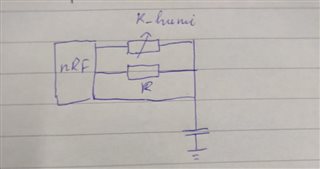
I am using timer 3 as a counter for my capacitor discharge time. Currently, the value of is always problematic because it shows with too many deviation values sometimes 15837, but other times 239 while the environment for the hr202 sensor remains unchanged. I am using nrf_drv_timer_capture() function to get that time value. So what am I encountering here?
this is my code and may schematic. Can someone help me?
void timer_event_handler(nrf_timer_event_t event_type, void *p_context) {}

const nrf_drv_timer_t TIMER = NRF_DRV_TIMER_INSTANCE(3);

static void config_timer()
{
    uint32_t err_code = NRF_SUCCESS;

    nrf_drv_timer_config_t timer_cfg;

    timer_cfg.frequency = NRF_TIMER_FREQ_1MHz;
    timer_cfg.mode = NRF_TIMER_MODE_TIMER;
    timer_cfg.bit_width = NRF_TIMER_BIT_WIDTH_16;
    timer_cfg.interrupt_priority = 6;
    timer_cfg.p_context = NULL;

    err_code = nrf_drv_timer_init(&TIMER, &timer_cfg, timer_event_handler);
}

static void human_begin_read(uint8_t type)
{
    nrf_gpio_cfg_output(HUMI_PIN);
    nrf_gpio_cfg_output(REF_PIN);
    nrf_gpio_cfg_output(READ_PIN);

    // clear pin
    nrf_gpio_pin_write(HUMI_PIN, 0);
    nrf_gpio_pin_write(REF_PIN, 0);
    nrf_gpio_pin_write(READ_PIN, 0);
    nrf_delay_ms(1);

    humi_state = HUMI_NORMAL;
    ovf_count = 0;
    humi_time = 0;

    nrf_gpio_cfg_input(READ_PIN, NRF_GPIO_PIN_NOPULL);
    if (type == REF)
    {
        nrf_gpio_cfg_default(HUMI_PIN);
        nrf_gpio_pin_write(REF_PIN, 1);
    }
    else
    {
        nrf_gpio_cfg_default(REF_PIN);
        nrf_gpio_pin_write(HUMI_PIN, 1);
    }

    uint32_t time_ticks = nrf_drv_timer_ms_to_ticks(&TIMER, 1000);
    nrf_drv_timer_extended_compare(
        &TIMER, NRF_TIMER_CC_CHANNEL0, time_ticks, NRF_TIMER_SHORT_COMPARE0_CLEAR_MASK, true);

    nrf_drv_timer_enable(&TIMER);
    while (nrf_gpio_pin_read(READ_PIN) == 0)
    {
    }

    humi_time = nrf_drv_timer_capture(&TIMER, NRF_TIMER_CC_CHANNEL0);

    nrf_drv_timer_clear(&TIMER);
    nrf_drv_timer_disable(&TIMER);

    humi_state = HUMI_SUCCESS;

    nrf_gpio_cfg_output(HUMI_PIN);
    nrf_gpio_cfg_output(REF_PIN);
    nrf_gpio_cfg_output(READ_PIN);

    // clear pin
    nrf_gpio_pin_write(HUMI_PIN, 0);
    nrf_gpio_pin_write(REF_PIN, 0);
    nrf_gpio_pin_write(READ_PIN, 0);
    nrf_delay_ms(1);
}