ADXL362 with nRF9160 DK not working

Hello Nordic Support,

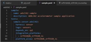
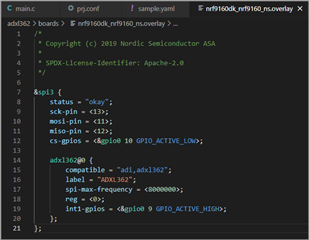
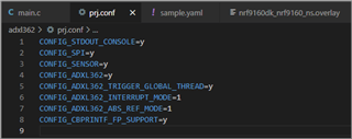
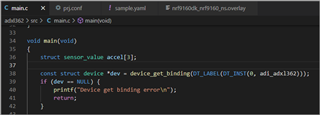
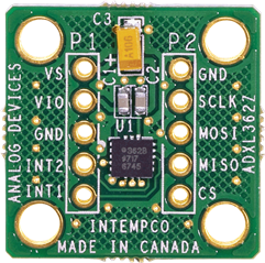
I started with a sensor sample project for ADXL362 Three Axis Accelerometer (https://github.com/zephyrproject-rtos/zephyr/tree/main/samples/sensor/adxl362) and connected to my nRF9160DK board. I used the same SPI lines that external memory is used on nRF9160DK board but a different Chip Select IO for the sensor. I am able to compile the code successfully but I am not able to bind the sensor. Can you please review and suggest what could be an issue?

Project:
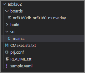
adxl362.zip

Parents
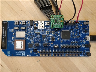
  • I am interfacing ADXL362Z board with nRF91DK as seen in the image below. The same sensor board is returning correct Part ID <F2> when connected to Arduino board. I have shared logic analyzer captures for both Arduino and nRF91 DK in my previous posts.

    The differences I can see between nRF91 DK SPI and Arduino board SPI waveform is that there is no delay between command and data output byte in Arduino but for nRF91 DK the delay is 16us for 1Mhz and 28us for 4Mhz. I am thinking this delay could be causing ADXL362 incorrect output.

    Can this delay be reduced or eliminated? Of is this inherent to SPI peripheral on SOC when SPI switch from write to read mode?

Reply
  • I am interfacing ADXL362Z board with nRF91DK as seen in the image below. The same sensor board is returning correct Part ID <F2> when connected to Arduino board. I have shared logic analyzer captures for both Arduino and nRF91 DK in my previous posts.

    The differences I can see between nRF91 DK SPI and Arduino board SPI waveform is that there is no delay between command and data output byte in Arduino but for nRF91 DK the delay is 16us for 1Mhz and 28us for 4Mhz. I am thinking this delay could be causing ADXL362 incorrect output.

    Can this delay be reduced or eliminated? Of is this inherent to SPI peripheral on SOC when SPI switch from write to read mode?

Children
  • Thanks for providing the this image. Is it correct that you have connected

    ADXL362

    Pin

    Overlay

    SCLK 

    SPI Communications Clock

    P0.15

    sck-pin = <19>;

    MOSI

    Master Output, Slave Input. SPI serial data input.

    P.016
    mosi-pin = <18>;

    MISO

    Master Input, Slave Output. SPI serial data output.

    P0.17
    miso-pin = <17>;

    CS

    SPI Chip Select, Active Low. Must be low during SPI communications.

    P0.18
    cs-gpios = <&gpio0 16 GPIO_ACTIVE_LOW>

    INT1

    Interrupt 1 Output. INT1 also serves as an input for external clocking.

    ?
    int1-gpios = <&gpio0 15 GPIO_ACTIVE_HIGH>;
Related