ADXL362 with nRF9160 DK not working

Hello Nordic Support,

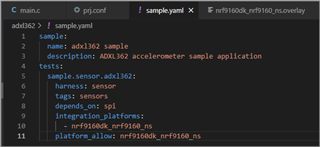
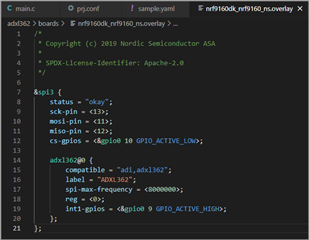
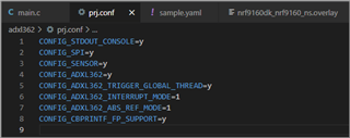
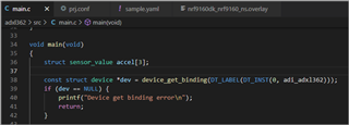
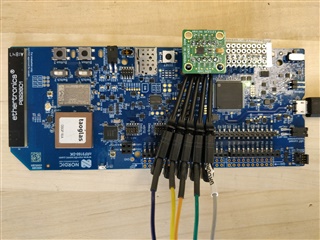
I started with a sensor sample project for ADXL362 Three Axis Accelerometer (https://github.com/zephyrproject-rtos/zephyr/tree/main/samples/sensor/adxl362) and connected to my nRF9160DK board. I used the same SPI lines that external memory is used on nRF9160DK board but a different Chip Select IO for the sensor. I am able to compile the code successfully but I am not able to bind the sensor. Can you please review and suggest what could be an issue?

Project:
adxl362.zip

Parents
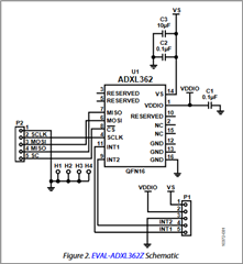
  • I managed to find the problem. When I connected the ADXL362 with P2 header of the nRF91 board the PIN (19,18,17,16) aligned with the SPI pins on ADXL362 P2 header, So I was able to connect it directly in to the header to keep signal path short for low signal distortion at 1.8V IOs, except the GND pin that I had to bend so as to not let it go in the headers. I am using power and GND pins on the second header P1 on ADXL362 board to provide power and GND from nRF91 board.

    From the schematic it looks like the GND on P2 pin 1 do not go to any specific GND pin on ADXL362 and terminates to board ground. But if I leave P2 header pin 1 GND not connected, ADXL362 respond with <F0> on Chip Id read command. And If I connect P2 header pin 1 GND to GND pin on nRF91DK then I  get proper <F2> response for Chip Id read command. This is something I do not understand. The ADXL362 respond but with value that is not documented in the data sheet.

    Today I removed all the jumper wires even for power and ground and connected everything with very small piece of wires between the headers to improve SPI signal quality at high speed. My observation is at 8Mhz even when two board are connected directly without any jumper wires, the clock signals distorts and looks triangle on oscilloscope because of the length of trace path from nRF91 to board headers to ADXL362 and IO voltage being 1.8V. Even at 4 Mhz clock signals are not perfectly square but has acceptable slew rate. Note: Slew rate measurement on oscilloscope was done with logic analyzer probes disconnected. Any SPI chip connected to headers of nRF91DK need to be clocked down to reduce signal distortion.

    I am running nRF91 SPI at 1Mhz and signals looks clean and square, even on 2 Mhz clock rate. And I am able to get correct Chip Id read response <F2> and  good X,Y&Z data from ADXL362.

    Still the requirement of connecting header P2 pin 1 GND to host board ground in addition to power and ground connection on P1 header of ADXL362 baffles me. But I have a workable solution now that I can proceed with.

  • Happy to hear you found the solution!

    Have a happy holiday!

Reply Children
No Data
Related