This discussion has been locked.
You can no longer post new replies to this discussion. If you have a question you can start a new discussion

nRF52840 + PPK2 - Source meter vs Ampere meter

Hi everyone,

I have just purchased the PPK2. I've noticed that there two methods two measure the current

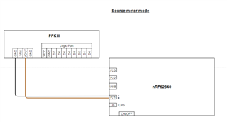
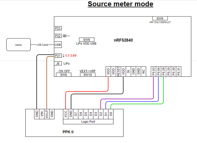
1. Source meter (the PPK2 provides power to the DUT)

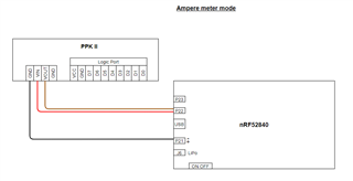
2. Ampere meter (use external power source for the DUT)

I am using the nRF52840 as DUT.

- Is there a recommended way for measuring the current (source vs ampere meter methods)?

- In case of Ampere meter mode, should I avoid powering the DUT from USB, or it doesn't matter?

- The source meter mode has the same accuracy as the ampere meter mode?

- If I want to use the digital channels I must connect Vcc and GND as well?

- In case of ampere meter mode how is the wiring between PPK2 and nRF52840 (I didn't find any documentation, I've just found this getting started tutorial but the wiring isn't clear). Could you confirm the following wirings?


Parents
  • Hello!

    Source meter mode is usually used when you want to measure the total current consumption of the board. Let's say that you have a battery powered design, then you can replace the battery with the PPK2 in source meter mode and see what the actual current draw from the battery will be.

    Ampere meter mode is used when you need to tap in to specific power domains in a design to see the current that goes to these domains. Or if the power supply can't be replaced with the PPK2.

    The accuracy is the same in both modes.

    If the DUT is an nRF52840 DK, you can choose to either use ampere meter mode or source meter mode. I think the source meter mode option is the best option as you will get the most accurate results and still be able to flash the DK without having to rewire anything (you only switch SW6 to nRF ONLY when measuring, and DEFAULT when flashing)

    1. Source meter mode:
      1. Power the nRF52 directly from P21 by using the SW10 (VEXT -> nRF)
      2. If SB40 is previously cut, put a jumper on P22.
      3. The USB should be left connected in order to power the rest of the DK (otherwise you will get leakage through the SWD interface)
      4. The nRF ONLY switch (SW6) should be set to nRF ONLY to avoid leakage currents
      5. In order to flash code set SW6 back to DEFAULT.
    2. Ampere meter mode:
      1. Measure current through the current measurement header (P22) (cut SB40)
      2. SW10 to off
      3. SW6 to DEFAULT
      4. Unplug the USB and power with a 3V clean supply on P21.
      5. Alternatively, you can leave the USB cable connected (and remove the supply on P21), but you may get 10 uA increased current, because of noise.

    The wiring in the drawings you posted is correct.

Reply
  • Hello!

    Source meter mode is usually used when you want to measure the total current consumption of the board. Let's say that you have a battery powered design, then you can replace the battery with the PPK2 in source meter mode and see what the actual current draw from the battery will be.

    Ampere meter mode is used when you need to tap in to specific power domains in a design to see the current that goes to these domains. Or if the power supply can't be replaced with the PPK2.

    The accuracy is the same in both modes.

    If the DUT is an nRF52840 DK, you can choose to either use ampere meter mode or source meter mode. I think the source meter mode option is the best option as you will get the most accurate results and still be able to flash the DK without having to rewire anything (you only switch SW6 to nRF ONLY when measuring, and DEFAULT when flashing)

    1. Source meter mode:
      1. Power the nRF52 directly from P21 by using the SW10 (VEXT -> nRF)
      2. If SB40 is previously cut, put a jumper on P22.
      3. The USB should be left connected in order to power the rest of the DK (otherwise you will get leakage through the SWD interface)
      4. The nRF ONLY switch (SW6) should be set to nRF ONLY to avoid leakage currents
      5. In order to flash code set SW6 back to DEFAULT.
    2. Ampere meter mode:
      1. Measure current through the current measurement header (P22) (cut SB40)
      2. SW10 to off
      3. SW6 to DEFAULT
      4. Unplug the USB and power with a 3V clean supply on P21.
      5. Alternatively, you can leave the USB cable connected (and remove the supply on P21), but you may get 10 uA increased current, because of noise.

    The wiring in the drawings you posted is correct.

Children
Related