Nordic,
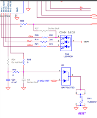
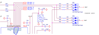
We've been using the nRF52832 for many years now. We have a custom board that uses SWCLK and SWDIO to flash our NRF52. We're getting set for production and I am working on our automated manufacturing rig. We have a python script that flashes a nordic with a soft device, bootloader, and then application. Some of the GPIO go to LEDs, so I can see what state the chip is in after programming. It had been working great then I started getting this problem where the LEDs didn't show up in the right state. I'd go to reflash the device, and then the SWD won't connect, and I could not erase the chip. I can hit our reset button, tied to the RESET pin on the IC, and nothing happens. Normally this button does a hard reset, where the LED goes away and (I believe) the chip loses power. Upon release of the reset, the board should initialize into the bootloader and the LED blinks red marking as such. But for these 'bricked' boards, the LED stays on throughout the reset button press. These two things: not able to reset the chip, and not being able to reflash the chip, these are quite alarming.
One piece of good news is the current drawn seems to be about 1 mA like when the Nordic is in low power state.
I've spent most all day going through devzone forums trying things, hoping to recover or at least explain my freeze-up.
When I go back into J Flash Lite, I can no longer ERASE the chip. Now it says
Connecting to J-Link...
Connecting to target...
ERROR: Could not connect to target.
Done.
Fine, I can try from the command utility. I use the jlink.exe tool, and go through the regular steps to connect and then try to erase. This also doesn't work:
J-Link>connect
Device "NRF52832_XXAA" selected.
Connecting to target via JTAG
InitTarget() start
InitTarget() end
TotalIRLen = ?, IRPrint = 0x..000000000000000000000000
InitTarget() start
InitTarget() end
TotalIRLen = ?, IRPrint = 0x..000000000000000000000000
InitTarget() start
InitTarget() end
TotalIRLen = ?, IRPrint = 0x..000000000000000000000000
InitTarget() start
InitTarget() end
TotalIRLen = ?, IRPrint = 0x..000000000000000000000000
Cannot connect to target.
Ok, now I try to use the nrfjprog tool. For reference I look up the version as
nrfjprog version: 10.15.1 external
JLinkARM.dll version: 7.58b
Then I do all kinds of commands to try and talk to my board. Here are some
>nrfjprog --recover --log
ERROR: [SeggerBackend] - JLinkARM.dll reported "-1", "An unknown error.".
ERROR: [SeggerBackend] - JLinkARM.dll reported "-1", "An unknown error.".
ERROR: [SeggerBackend] - JLinkARM.dll reported "-1", "An unknown error.".
ERROR: [SeggerBackend] - JLinkARM.dll reported "-1", "An unknown error.".
ERROR: [SeggerBackend] - JLinkARM.dll reported "-1", "An unknown error.".
ERROR: [SeggerBackend] - JLinkARM.dll reported "-1", "An unknown error.".
ERROR: [SeggerBackend] - JLinkARM.dll reported "-1", "An unknown error.".
ERROR: [ nRFXX] - Device does not have an ARM debug port.
ERROR: [SeggerBackend] - JLinkARM.dll reported "-1", "An unknown error.".
ERROR: nrfjprog could not identify the target device. This may be due to an
ERROR: invalid family argument, a problem with your device, or nrfjprog may
ERROR: not yet support your device.
ERROR: Please check the family argument passed, or upgrade nrfjprog to a more
ERROR: recent version.
>nrfjprog -e
ERROR: nrfjprog could not identify the target device. This may be due to an
ERROR: invalid family argument, a problem with your device, or nrfjprog may
ERROR: not yet support your device.
ERROR: Please check the family argument passed, or upgrade nrfjprog to a more
ERROR: recent version.
NOTE: For additional output, try running again with logging enabled (--log).
NOTE: Any generated log error messages will be displayed.
>nrfjprog -d --family nrf52 --log
ERROR: Unable to connect to a debugger.
ERROR: [ nRF52] - Debug probe is not connected to an NRF52 series device.
ERROR: The --family option given with the command (or the default from
ERROR: nrfjprog.ini) does not match the device connected.
I know the segger and cables and everything are correct, I HAD been able to program this and other boards. But during development of the python script, I've 'bricked' 5 of my boards. I only have 2 left. So I need to get to the bottom of this.
I don't understand how something could ever make the SWCLK SWDIO not able to erase the chip. What am I missing, please help.
environment: windows 10