
Hello, I test SAADC on nRF52810, when I short gound to AIN0, the output is 0 normally, and when I add nothing to Pin I0(AIN0), the output is around 1056(Figure0), however when I just connect Dupont Line without anything to Pin I0(AIN0), the output seems have sin noise, the output data and graph is showing in Figure1 and Figure2, then I cant read useful information from AIN0 when I connect load with Dupont Line. The Amplifier of AIN0 is shown in Figure3 and A0 is connect with AIN0 shown in Figure4. Then configuration of SAADC and test case is shown below:
what should I do to solve this problem, wishing for reply
//define for ADC
#define SAMPLES_IN_BUFFER 3
volatile uint8_t state = 1;
#define ADC_REF 600
#define ADC_BIT 4096
#define ADC_GAIN 6
#define ADC_VAL(ADC_VALUE) ((((ADC_VALUE) *ADC_REF) / ADC_BIT) * ADC_GAIN)

static const nrf_drv_timer_t m_timer = NRF_DRV_TIMER_INSTANCE(2);
static nrf_saadc_value_t     m_buffer_pool[2][SAMPLES_IN_BUFFER];
static nrf_ppi_channel_t     m_ppi_channel;

// <e> NRFX_SAADC_ENABLED - nrfx_saadc - SAADC peripheral driver
//==========================================================
#ifndef NRFX_SAADC_ENABLED
#define NRFX_SAADC_ENABLED 1
#endif
// <o> NRFX_SAADC_CONFIG_RESOLUTION  - Resolution

// <0=> 8 bit
// <1=> 10 bit
// <2=> 12 bit
// <3=> 14 bit

#ifndef NRFX_SAADC_CONFIG_RESOLUTION
#define NRFX_SAADC_CONFIG_RESOLUTION 2
#endif

// <o> NRFX_SAADC_CONFIG_OVERSAMPLE  - Sample period

// <0=> Disabled
// <1=> 2x
// <2=> 4x
// <3=> 8x
// <4=> 16x
// <5=> 32x
// <6=> 64x
// <7=> 128x
// <8=> 256x

#ifndef NRFX_SAADC_CONFIG_OVERSAMPLE
#define NRFX_SAADC_CONFIG_OVERSAMPLE 0
#endif

// <q> NRFX_SAADC_CONFIG_LP_MODE  - Enabling low power mode


#ifndef NRFX_SAADC_CONFIG_LP_MODE
#define NRFX_SAADC_CONFIG_LP_MODE 0


#define NRFX_SAADC_DEFAULT_CHANNEL_CONFIG_SE(PIN_P) \
{                                                   \
    .resistor_p = NRF_SAADC_RESISTOR_DISABLED,      \
    .resistor_n = NRF_SAADC_RESISTOR_DISABLED,      \
    .gain       = NRF_SAADC_GAIN1_6,                \
    .reference  = NRF_SAADC_REFERENCE_INTERNAL,     \
    .acq_time   = NRF_SAADC_ACQTIME_5US,           \
    .mode       = NRF_SAADC_MODE_SINGLE_ENDED,      \
    .burst      = NRF_SAADC_BURST_DISABLED,         \
    .pin_p      = (nrf_saadc_input_t)(PIN_P),       \
    .pin_n      = NRF_SAADC_INPUT_DISABLED          \
}
void saadc_callback(nrf_drv_saadc_evt_t const * p_event)
{
    if (p_event->type == NRF_DRV_SAADC_EVT_DONE)
    {
        ret_code_t err_code;
        err_code = nrf_drv_saadc_buffer_convert(p_event->data.done.p_buffer, SAMPLES_IN_BUFFER);
        APP_ERROR_CHECK(err_code);

        int i;
        NRF_LOG_INFO("ADC event number: %d", (int)m_adc_evt_counter);
//				printf("%d|%d|%d|%d|%d|%d|%d|%d\n",
//						adc_data_16[0],
//						adc_data_16[1],
//						adc_data_16[2],
//						adc_data_16[3],
//						adc_data_16[4],
//						adc_data_16[5],
//						adc_data_16[6],
//						adc_data_16[7]);
//				int all=0;
//        for (i = 0; i < SAMPLES_IN_BUFFER; i++)
//        {
//					all+=p_event->data.done.p_buffer[i];
//					//NRF_LOG_INFO("ADC[%d] value is : %d", i, data);
//        }
				printf("%d\n",ADC_VAL(p_event->data.done.p_buffer[0]));
        m_adc_evt_counter++;
    }
}
void saadc_init(void)
{
    ret_code_t err_code;
    nrf_saadc_channel_config_t channel0_config =
        NRF_DRV_SAADC_DEFAULT_CHANNEL_CONFIG_SE(NRF_SAADC_INPUT_AIN0);
		nrf_saadc_channel_config_t channel1_config =
        NRF_DRV_SAADC_DEFAULT_CHANNEL_CONFIG_SE(NRF_SAADC_INPUT_AIN1);
		nrf_saadc_channel_config_t channel2_config =
        NRF_DRV_SAADC_DEFAULT_CHANNEL_CONFIG_SE(NRF_SAADC_INPUT_AIN2);
		nrf_saadc_channel_config_t channel3_config =
        NRF_DRV_SAADC_DEFAULT_CHANNEL_CONFIG_SE(NRF_SAADC_INPUT_AIN3);
		nrf_saadc_channel_config_t channel4_config =
        NRF_DRV_SAADC_DEFAULT_CHANNEL_CONFIG_SE(NRF_SAADC_INPUT_AIN4);
		nrf_saadc_channel_config_t channel5_config =
        NRF_DRV_SAADC_DEFAULT_CHANNEL_CONFIG_SE(NRF_SAADC_INPUT_AIN5);
		nrf_saadc_channel_config_t channel6_config =
        NRF_DRV_SAADC_DEFAULT_CHANNEL_CONFIG_SE(NRF_SAADC_INPUT_AIN6);
		nrf_saadc_channel_config_t channel7_config =
        NRF_DRV_SAADC_DEFAULT_CHANNEL_CONFIG_SE(NRF_SAADC_INPUT_AIN7);

    err_code = nrf_drv_saadc_init(NULL, saadc_callback);
    APP_ERROR_CHECK(err_code);

    err_code = nrf_drv_saadc_channel_init(0, &channel0_config);
    APP_ERROR_CHECK(err_code);
//		err_code = nrf_drv_saadc_channel_init(1, &channel1_config);
//    APP_ERROR_CHECK(err_code);
//		err_code = nrf_drv_saadc_channel_init(2, &channel2_config);
//    APP_ERROR_CHECK(err_code);
//		err_code = nrf_drv_saadc_channel_init(3, &channel3_config);
//    APP_ERROR_CHECK(err_code);
//		err_code = nrf_drv_saadc_channel_init(4, &channel4_config);
//    APP_ERROR_CHECK(err_code);
//		err_code = nrf_drv_saadc_channel_init(5, &channel5_config);
//    APP_ERROR_CHECK(err_code);
//		err_code = nrf_drv_saadc_channel_init(6, &channel6_config);
//    APP_ERROR_CHECK(err_code);
//		err_code = nrf_drv_saadc_channel_init(7, &channel7_config);
//    APP_ERROR_CHECK(err_code);

    err_code = nrf_drv_saadc_buffer_convert(m_buffer_pool[0], SAMPLES_IN_BUFFER);
    APP_ERROR_CHECK(err_code);

    err_code = nrf_drv_saadc_buffer_convert(m_buffer_pool[1], SAMPLES_IN_BUFFER);
    APP_ERROR_CHECK(err_code);

}
void saadc_sampling_event_init(void)
{
    ret_code_t err_code;

    err_code = nrf_drv_ppi_init();
    APP_ERROR_CHECK(err_code);

    nrf_drv_timer_config_t timer_cfg = NRF_DRV_TIMER_DEFAULT_CONFIG;
    timer_cfg.bit_width = NRF_TIMER_BIT_WIDTH_32;
    err_code = nrf_drv_timer_init(&m_timer, &timer_cfg, timer_handler);
    APP_ERROR_CHECK(err_code);

    /* setup m_timer for compare event every 2000ms */
    uint32_t ticks = nrf_drv_timer_ms_to_ticks(&m_timer, 5);
    nrf_drv_timer_extended_compare(&m_timer,
                                   NRF_TIMER_CC_CHANNEL0,
                                   ticks,
                                   NRF_TIMER_SHORT_COMPARE0_CLEAR_MASK,
                                   false);
    nrf_drv_timer_enable(&m_timer);

    uint32_t timer_compare_event_addr = nrf_drv_timer_compare_event_address_get(&m_timer,
                                                                                NRF_TIMER_CC_CHANNEL0);
    uint32_t saadc_sample_task_addr   = nrf_drv_saadc_sample_task_get();

    /* setup ppi channel so that timer compare event is triggering sample task in SAADC */
    err_code = nrf_drv_ppi_channel_alloc(&m_ppi_channel);
    APP_ERROR_CHECK(err_code);

    err_code = nrf_drv_ppi_channel_assign(m_ppi_channel,
                                          timer_compare_event_addr,
                                          saadc_sample_task_addr);
    APP_ERROR_CHECK(err_code);
}
int main(void)
{
    bool erase_bonds;

    // Initialize.
    log_init();
    timers_init();
		uart_init();
    //buttons_leds_init(&erase_bonds);
    power_management_init();
    ble_stack_init();
    gap_params_init();
    gatt_init();
    services_init();
    advertising_init();
    conn_params_init();

		saadc_init();
    saadc_sampling_event_init();
    saadc_sampling_event_enable();

    // Start execution.
    printf("\r\nUART started.\r\n");
    advertising_start();
    // Enter main loop.
    for (;;)
    {
        idle_state_handle();
    }
}
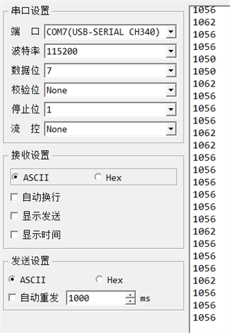
Figure0
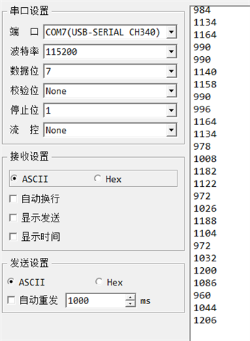
Figure1
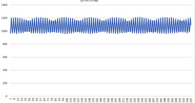
Figure2
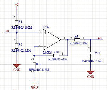
Figure3
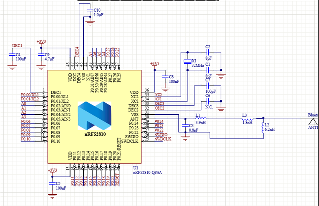
Figure4

