This discussion has been locked.
You can no longer post new replies to this discussion. If you have a question you can start a new discussion

Generating clock to mimic 48kHz sample clock for I2S device

Hi everyone, 

I am working on interfacing the nRF52840DK with a 24-bit mems microphone INMP441 through the I2S peripheral. As multi-sources pointed out that the nRF52840 does not support 32-bit word size. (ie. WS (LRCLK) frame = 64 BCLK pulses wide) and 48kHz sampling.

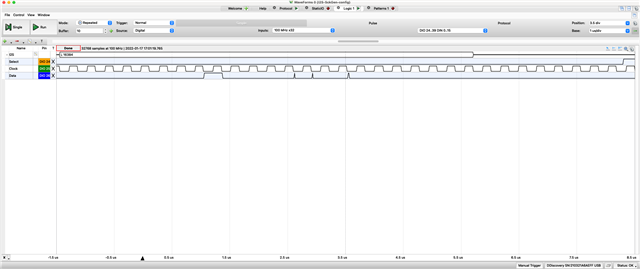
As the workaround, I configured the nRF52840 as an I2S slave and provided the BCLK (48kHz) and LRCLK(3.125MHz) externally from a signal generator. The I2S works completely fine. 

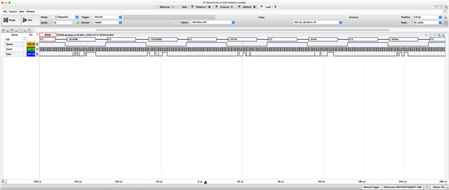
As moving forward, I have tried to use the PMWs to mimic the BCLK (48kHz) and LRCLK(3.125MHz) by following this GitHub repo: https://github.com/gregtomasch/nRF52_24-bit-_I2S_Microphone_Audio_Recording_Utility. However, the two PMW signals are not in sync and the output is garbled.

As a result, I would like to know is there any alternative that I can generate two in-sync clock signals from PMW or other peripheral?

Many Thanks
Anthony

  • Hi,

    I took a quick look at the code in the 3rd party repo.

    I see that the PWM clocks uses 2 different timers, and it's started like this:

        app_pwm_enable(&PWM1);
        app_pwm_enable(&PWM2);

    So there will be a slight delay there between when the clocks start.

    A workaround could be to use PPI to start the timers instead.

    Modify app_pwm_enable so that it does not start the timer immediately.

    i.e. remove: nrf_drv_timer_enable(p_instance->p_timer);

    and create a new function for starting the timers at the same time, a function that is called right after the two calls to app_pwm_enable().

    In this function, you could e.g. connect a EGU event to start the timers. E.g. connect EGU_event to timer0 start, and fork the event to start timer1 as well. Then trigger the EGU event, by writing to the corresponding EGU TASKS_TRIGGER.

  • Hi Sigurd,

    Thank you for your reply. Since I am quite a beginner at NRF MCU, I may ask some noobie questions.

    For using the EGU with PPI, if I understand correctly, I should use the EGU to first trigger an event from EGU, and then I can feed the address of this triggered event into PPI and then link up with the task to start timer0 (NRF_TIMER_TASK_START) and subsequently fork the same event with the task to start timer1.  like this:

    I have tried the above approach, unfortunately, I cannot get both timers started. 

    Here are a few things I suspect that I did wrong:

    1. I misunderstand the whole procedures
    2. I am not sure whether I successfully trigger the event @ EGU0
    3. I feed the wrong address of EGU_event into nrf_drv_ppi_channel_assign() 
    4. Other reasons, I didn't spot..........

    I also have the code snippet attached below.  once again thanks for your help.

    Anthony

    static void ppi_init(app_pwm_t const * const p_instance1, app_pwm_t const * const p_instance2)
    {
        uint32_t err_code = NRF_SUCCESS;
       	
       	err_code = nrf_drv_ppi_init();
        APP_ERROR_CHECK(err_code);
    
        err_code = nrf_drv_ppi_channel_alloc(&m_ppi_channel1);
        APP_ERROR_CHECK(err_code);
    
        err_code = nrf_drv_ppi_channel_assign(m_ppi_channel1,nrf_egu_event_triggered_address_get(NRF_EGU0,0),nrf_drv_timer_task_address_get(p_instance1->p_timer,NRF_TIMER_TASK_START));
        
        err_code = nrf_drv_ppi_channel_fork_assign(m_ppi_channel1,nrf_drv_timer_task_address_get(p_instance2->p_timer, NRF_TIMER_TASK_START));
    }

    int main(void)
    {
     
        ........
        
        ppi_init(&PWM1,&PWM2);
    
        /* 1-channel PWM, 3.165MHz, output on Pin 13. */
        app_pwm_config_t pwm1_cfg = APP_PWM_DEFAULT_CONFIG_1CH(5L, 13); // 16Mhz/5 = 3.165Mhz
    
        /* 1-channel PWM, 48kHz, output on Pin 14. */
        app_pwm_config_t pwm2_cfg = APP_PWM_DEFAULT_CONFIG_1CH(333L, 14); //16Mhz/333 = 48kHz
    
        /* Initialize PWM. */
        err_code = app_pwm_ticks_init(&PWM1,&pwm1_cfg,pwm_ready_callback);
        APP_ERROR_CHECK(err_code);
        err_code = app_pwm_ticks_init(&PWM2,&pwm2_cfg,pwm_ready_callback);
        APP_ERROR_CHECK(err_code);
        
        app_pwm_enable(&PWM1);
        app_pwm_enable(&PWM2);
    
        nrf_egu_task_trigger(NRF_EGU0,NRF_EGU_TASK_TRIGGER0);
        
        app_pwm_channel_duty_set(&PWM1, 0, 50);
        app_pwm_channel_duty_set(&PWM2, 0, 50);
    
        .........
    }

  • Hi,

    I managed to enable both timers as the same, as I forgot to add 

    nrf_drv_ppi_channel_enable(m_ppi_channel1);

    to the ppi_init()

    However, I still got garbled output, I am wondering what else can I do to get the valid I2S data ?
    (Of course, I can get valid data by using other mcu to generat I2S clocks).

    I got the following from my logic analyzer:

    There is something wired that I did something wrong:

    1.  "spike" in the data line like the following 
    2.  All "0" occurs only when WS is High

    Any suggestions on these issues or workaround, or fundamentally I cannot sample I2S data @48kHz.

    Thanks 
    Anthony 

  • Hi,

    PMW signals are not in sync

    Are the PWM signals now in sync?

    You could try to start the HFCLK from the crystal oscillator, and see if that improves anything.

    //Start HFCLK from crystal oscillator
    NRF_CLOCK->TASKS_HFCLKSTART = 1;
    while (NRF_CLOCK->EVENTS_HFCLKSTARTED == 0);

  • Yes, they are in-sync. I tried to low the sampling frequency, while maintaining the frequency of SCLK to WS 1:64, but it is still not working.

    Apart from the PWM third-part library, I also tried another approach by using GPIOTE, TIMER, and PPI to generate pulses. I also did what you suggested above in this approach, however it is no luck. 

     (it might be off topic, but how can I generate 3.125MHz clock from this approach,
    as changing the CC value and prescaler cannot cannot lead me to generate3.125MHz clock)


    void sclk_gen(void)
    {
        // Set up GPIO as output
        nrf_gpio_range_cfg_output(13, 14);
        
        // Start high frequency clock
        NRF_CLOCK->TASKS_HFCLKSTART = 1;
        while (NRF_CLOCK->EVENTS_HFCLKSTARTED == 0)
        {
            // Wait for clock to start
        }
        NRF_CLOCK->EVENTS_HFCLKSTARTED = 0;
        
        // Configure GPIOTE to toggle pin 13
        NRF_GPIOTE->CONFIG[0] = GPIOTE_CONFIG_MODE_Task << GPIOTE_CONFIG_MODE_Pos |
                                GPIOTE_CONFIG_POLARITY_Toggle << GPIOTE_CONFIG_POLARITY_Pos |
                                13 << GPIOTE_CONFIG_PSEL_Pos | 
                                GPIOTE_CONFIG_OUTINIT_Low << GPIOTE_CONFIG_OUTINIT_Pos;
        
        // Configure GPIOTE to toggle pin 14                     
        NRF_GPIOTE->CONFIG[1] = GPIOTE_CONFIG_MODE_Task << GPIOTE_CONFIG_MODE_Pos |
                            GPIOTE_CONFIG_POLARITY_Toggle << GPIOTE_CONFIG_POLARITY_Pos |
                            14 << GPIOTE_CONFIG_PSEL_Pos | 
                            GPIOTE_CONFIG_OUTINIT_Low << GPIOTE_CONFIG_OUTINIT_Pos;
    
        // Set up timer
        NRF_TIMER1->PRESCALER = 0;
        NRF_TIMER1->CC[0] = 16; // Adjust the output frequency by adjusting the CC.
        NRF_TIMER1->SHORTS = TIMER_SHORTS_COMPARE0_CLEAR_Enabled << TIMER_SHORTS_COMPARE0_CLEAR_Pos;
        //NRF_TIMER1->TASKS_START = 1;
    
        NRF_TIMER0->PRESCALER = 0;
        NRF_TIMER0->CC[0] = 250; // Adjust the output frequency by adjusting the CC.
        NRF_TIMER0->SHORTS = TIMER_SHORTS_COMPARE0_CLEAR_Enabled << TIMER_SHORTS_COMPARE0_CLEAR_Pos;
        //NRF_TIMER0->TASKS_START = 1;
            
        // Set up PPI to connect the timer compare event with the GPIOTE toggle task
        NRF_PPI->CH[0].EEP = (uint32_t) &NRF_TIMER1->EVENTS_COMPARE[0];
        NRF_PPI->CH[0].TEP = (uint32_t) &NRF_GPIOTE->TASKS_OUT[0];
        
        NRF_PPI->CH[1].EEP = (uint32_t) &NRF_TIMER0->EVENTS_COMPARE[0];
        NRF_PPI->CH[1].TEP = (uint32_t) &NRF_GPIOTE->TASKS_OUT[1];
    
        NRF_PPI->CH[2].EEP =    (uint32_t) &NRF_EGU0->EVENTS_TRIGGERED[0];
        NRF_PPI->CH[2].TEP =   (uint32_t)  &NRF_TIMER0->TASKS_START;
        NRF_PPI->FORK[2].TEP = (uint32_t)  &NRF_TIMER1->TASKS_START;
        
        NRF_PPI->CHENSET = PPI_CHENSET_CH0_Enabled << PPI_CHENSET_CH0_Pos;
        NRF_PPI->CHENSET = PPI_CHENSET_CH1_Enabled << PPI_CHENSET_CH1_Pos;
        NRF_PPI->CHENSET = PPI_CHENSET_CH2_Enabled << PPI_CHENSET_CH2_Pos;
    
        NRF_EGU0->TASKS_TRIGGER[0] = 1;
    }

    Once again thank for you help and quick response 

    Anthony

Related