This discussion has been locked.
You can no longer post new replies to this discussion. If you have a question you can start a new discussion

using spi_write() & spi_read() not behaving the same as spi_transceive() for spi data in provided spi sample

Hi,

I tried running an spi sample program with code as in below, shorted the MOSI and MISO pins and data was visibly received in print statement:

#include <zephyr.h>

#include <sys/printk.h>
#include <drivers/spi.h>
#include <drivers/gpio.h>


uint32_t freq = 4000000;
static const struct spi_config spi_cfg = {freq,(SPI_WORD_SET(8) | SPI_TRANSFER_MSB),0,nullptr};


const device * spi_dev;


static void spi_init(void)
{
const char* spiName = "SPI_1";
//const char* const spiName = "spi1";
spi_dev = device_get_binding(spiName);


if (spi_dev == NULL) {
printk("Could not get %s device\n", spiName);
return;
}
}


void spi_test_send(void)
{
int err;
static uint32_t tx_buffer[1]={0x05};
//static uint8_t tx_buffer = 128;
//static char tx_buffer[3]={'D','s','s'};
static uint32_t rx_buffer[1];
//static uint8_t rx_buffer;


const struct spi_buf tx_buf = {
.buf = tx_buffer,
.len = sizeof(tx_buffer)
};
const struct spi_buf_set tx = {
.buffers = &tx_buf,
.count = 1
};


struct spi_buf rx_buf = {
.buf = rx_buffer,
.len = sizeof(rx_buffer),
};
const struct spi_buf_set rx = {
.buffers = &rx_buf,
.count = 1
};


err = spi_transceive(spi_dev, &spi_cfg, &tx, &rx);

if (err) {
printk("SPI error: %d\n", err);
} else {
/* Connect MISO to MOSI for loopback */
printk("TX sent: %d\n", tx_buffer[0]);
printk("RX recv: %d\n", rx_buffer[0]);

}
}


void main(void)
{
printk("SPIM Example\n");
spi_init();


while (1) {
spi_test_send();
k_sleep(K_SECONDS(1));
}
}

While in the same code if i use spi_write( ) & spi_read( ) apis, which inturn call spi transceive, I am not receiving any data, code as in below:

#include <zephyr.h>

#include <sys/printk.h>
#include <drivers/spi.h>
#include <drivers/gpio.h>


uint32_t freq = 4000000;
static const struct spi_config spi_cfg = {freq,(SPI_WORD_SET(8) | SPI_TRANSFER_MSB),0,nullptr};


const device * spi_dev;


static void spi_init(void)
{
const char* spiName = "SPI_1";
//const char* const spiName = "spi1";
spi_dev = device_get_binding(spiName);


if (spi_dev == NULL) {
printk("Could not get %s device\n", spiName);
return;
}
}


void spi_test_send(void)
{
int err;
static uint32_t tx_buffer[1]={0x05};
//static uint8_t tx_buffer = 128;
//static char tx_buffer[3]={'D','s','s'};
static uint32_t rx_buffer[1];
//static uint8_t rx_buffer;


const struct spi_buf tx_buf = {
.buf = tx_buffer,
.len = sizeof(tx_buffer)
};
const struct spi_buf_set tx = {
.buffers = &tx_buf,
.count = 1
};


struct spi_buf rx_buf = {
.buf = rx_buffer,
.len = sizeof(rx_buffer),
};
const struct spi_buf_set rx = {
.buffers = &rx_buf,
.count = 1
};


err = spi_write(spi_dev, &spi_cfg, &tx);
err = spi_read(spi_dev, &spi_cfg, &rx);

if (err) {
printk("SPI error: %d\n", err);
} else {
/* Connect MISO to MOSI for loopback */
printk("TX sent: %d\n", tx_buffer[0]);
printk("RX recv: %d\n", rx_buffer[0]);

}
}


void main(void)
{
printk("SPIM Example\n");
spi_init();


while (1) {
spi_test_send();
k_sleep(K_SECONDS(1));
}
}

I am getting just -1 in receive buffer.

Kindly suggest what i can do to make spi_write & spi_read work..?

  • Hi,


    shorted the MOSI and MISO pins and data was visibly received in print statement
    While in the same code if i use spi_write( ) & spi_read( ) apis, which inturn call spi transceive, I am not receiving any data, code as in below:

    Shorting MOSI to MISO and receiving a valid output only works if you run in full duplex, ie. send while simultaneously receiving.

    spi_write omits the RX buffer, while spi_read omits the TX buffer:

    https://github.com/nrfconnect/sdk-zephyr/blob/v2.7.0-ncs1/include/drivers/spi.h#L559


    Kind regards,

    Håkon

  • Hello Hakan,

    Noted with Thanks,

    Now I am running the following code on one board (bl653):

    void main(void)
    {
        uint32_t freq = 4000000;
        printk("SPIM Example\n");
    
        const char *spiName = "SPI_1";
        // const char* const spiName = "spi1";
        spi_dev = device_get_binding(spiName);
    
        gpio_dev = device_get_binding("GPIO_0");
        static const struct spi_cs_control spi_cs = {gpio_dev, 0, 23, (GPIO_ACTIVE_HIGH)};
    
        static struct spi_config spi_cfg;
        spi_cfg.frequency = freq; //= {freq, (SPI_WORD_SET(8) | SPI_TRANSFER_MSB), 0, &spi_cs};
    
        spi_cfg.operation |= (SPI_OP_MODE_MASTER | SPI_WORD_SET(8) | SPI_TRANSFER_MSB | SPI_MODE_CPHA);
        spi_cfg.slave = 0;
        spi_cfg.cs = &spi_cs;
    
        gpio_pin_configure(gpio_dev, 23, (GPIO_OUTPUT_ACTIVE | GPIO_ACTIVE_HIGH));
    
        if (spi_dev == NULL)
        {
            printk("Could not get %s device\n", spiName);
            return;
        }
    
    
        int err;
        static uint8_t tx_buffer[1] = {0x08};
    
        static uint8_t rx_buffer[1];
    
        const struct spi_buf tx_buf = {
            .buf = tx_buffer,
            .len = sizeof(tx_buffer)};
        const struct spi_buf_set tx = {
            .buffers = &tx_buf,
            .count = 1};
    
    
        while (1)
        {
            gpio_pin_set(gpio_dev, 23, 1);
            gpio_pin_set(gpio_dev, 23, 0);
            err = spi_write(spi_dev, &spi_cfg, &tx);
            gpio_pin_set(gpio_dev, 23, 1);
            
            if (err)
            {
                printk("SPI error: %d\n", err);
            }
            else
            {
                /* Connect MISO to MOSI for loopback */
                // printk("TX sent: %d\n", tx_buffer[0]);
            }
    
            k_sleep(K_MSEC(1));
        }
    }

    With an overlay file as: 

    &spi1 {
    	compatible = "nordic,nrf-spim";
    	status = "okay";
    	sck-pin = <41>;
    	mosi-pin = <40>;
    	miso-pin = <4>;
    	cs-gpios = <&gpio0 23 0>;
    };

    Above board is master & it's data I am able to see on USB logic analyzer.

    Now I am using another board (bl653) running slave driver & configured as slave, with the CLK,MOSI, MISO & cs pins connected between the two boards, the slave board is running the below code:

    void main(void)
    {
        uint32_t freq = 4000000;
        printk("SPIM Example\n");
        
        const char *spiName = "SPI_1";
        
        spi_dev = device_get_binding(spiName);
    
        gpio_dev = device_get_binding("GPIO_0");
        static const struct spi_cs_control spi_cs = {gpio_dev, 0, 23, (GPIO_ACTIVE_HIGH)};
        gpio_pin_configure(gpio_dev, 23, (GPIO_INPUT | GPIO_ACTIVE_HIGH));
        
        static struct spi_config spi_cfg;
        spi_cfg.frequency = freq; 
        
        spi_cfg.operation |= (SPI_OP_MODE_SLAVE | SPI_WORD_SET(8) | SPI_TRANSFER_MSB | SPI_MODE_CPHA);
        spi_cfg.slave = 1;
        spi_cfg.cs = &spi_cs;


        if (spi_dev == NULL)
        {
            printk("Could not get %s device\n", spiName);
            return;
        }
        //////////////////////////////
    
        int err;
    
    
        static uint8_t rx_buffer[1];
    
    
        struct spi_buf rx_buf = {
            .buf = rx_buffer,
            .len = sizeof(rx_buffer),
        };
        const struct spi_buf_set rx = {
            .buffers = &rx_buf,
            .count = 1};
    
        while (1)
        {
    
            err = spi_read(spi_dev, &spi_cfg, &rx);
            if (err)
            {
                printk("SPI error: %d\n", err);
            }
            else
            {
                /* Connect MISO to MOSI for loopback */
                // printk("TX sent: %d\n", tx_buffer[0]);
                printk("RX recv: %d\n", rx_buffer[0]);
            }
    
            k_sleep(K_MSEC(1));
        }
    }

    with it's overlay as:

    &spi1 {
    	compatible = "nordic,nrf-spis";
    	status = "okay";
    	sck-pin = <41>;
    	mosi-pin = <40>;
    	miso-pin = <4>;
    	cs-gpios = <&gpio0 23 0>;
    	csn-pin = <23>;
        def-char = <0xFF>;
    };


    Even in this case, slave board is not printing the received data.

    I have to use spi_write( ) on one board & spi_read( ) on another board for my application, but I am unable to transmit & receive. And I couldn't find any sample code of such arrangement.

    Request you to help me make this arrangement work.

    Thanks,

    Ubaid

  • You should scope your SPI lines, using a logic analyzer, to see how they behave.

    In your SPIM implementation, you specify the spi_cs pin, but also override this in the main-loop? That does not look correct.

    Kind regards,

    Håkon

  • Hello Hakan,

    but also override this in the main-loop

    So I am to understand that spi driver takes care of cs pin handling as per the cs details given in dts & I do not need to explicitly pull cs pin..? 
    Kindly confirm.


    Now, moving ahead, I found some examples from github:
    https://github.com/foldedtoad/spi_slave

    Since, these were working for others, i built the same for me.

    Yet I am not receiving the data:

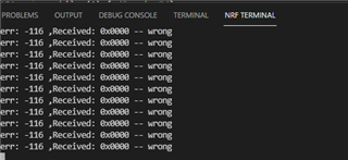
    It prints "Received: 0x0000"

    For your kind reference, attaching all my project the files herein, as is executed on bl653, which is acting as master:

    Code:

    /**
     * Copyright (c) 2019 - Callender-Consulting. LLC
     *
     *   You should have received a copy of the GNU General Public License.
     *   see <https://www.gnu.org/licenses/>.
     * 
     */
    #include <string.h>
    #include <errno.h>
    #include <zephyr.h>
    #include <sys/printk.h>
    #include <device.h>
    #include <drivers/spi.h>
    
    #define STACKSIZE 1024
    #define PRIORITY 99
    
    /*---------------------------------------------------------------------------*/
    /*                                                                           */
    /*---------------------------------------------------------------------------*/
    
    #define SPI_MASTER_BUS_NAME     		DT_INST_0_NORDIC_NRF_SPI_LABEL
    #define SPI_MASTER_GPIOS_NAME    		DT_ALIAS_GPIO_0_LABEL
    #define SPI_MASTER_GPIO_IRQ_PIN  		DT_ALIAS_SPI_0_CSN_PIN
    
    /* Needs to be aligned with the SPI master buffer size */
    #define SPI_MAX_MSG_LEN         255
    
    typedef struct spi_master_msg {
    	uint32_t       length;
        uint8_t        data [SPI_MAX_MSG_LEN];
    } spi_master_msg_t;
    
    ////////////////////////////////////////////////////////////////////////////////////////////////////////////
    /*---------------------------------------------------------------------------*/
    /*                                                                           */
    /*---------------------------------------------------------------------------*/
    int spi_master_write(struct device * spi, 
                         struct spi_config * spi_cfg,
                         uint16_t * data)
    {
        struct spi_buf bufs = {
                .buf = data,
                .len = 2
        };
        struct spi_buf_set tx = {
            .buffers = &bufs
        };
    
        tx.count = 1;
    
        return spi_write(spi, spi_cfg, &tx);
    }
    
    
    /*---------------------------------------------------------------------------*/
    /*                                                                           */
    /*---------------------------------------------------------------------------*/
    int spi_master_read(struct device * spi, 
                        struct spi_config * spi_cfg,
                        uint16_t * data)
    {
        struct spi_buf bufs = {
                .buf = data,
                .len = 2
        };
        struct spi_buf_set rx = {
            .buffers = &bufs
        };
    
        rx.count = 1;
    
        return spi_read(spi, spi_cfg, &rx);
    }
    
    /*---------------------------------------------------------------------------*/
    /*                                                                           */
    /*---------------------------------------------------------------------------*/
    void spi_master_init(void)
    {
        struct device * spi;
        struct spi_config spi_cfg;
        struct spi_cs_control cs_ctrl;
    
        uint16_t tx_data = 0x1234;
        uint16_t rx_data = 0;
    
        printk("SPI Master example application\n");
    
        printk("rx_data buffer at %p\n", &rx_data);
    
        spi = device_get_binding("SPI_1");
        if (!spi) {
            printk("Could not find SPI driver\n");
            return;
        }
    
        cs_ctrl.gpio_dev = device_get_binding("GPIO_0");
        cs_ctrl.gpio_pin = 23;
        cs_ctrl.delay = 0;
    
        /*
         *  SPI controller configuration structure for the nRF52 series.
         *
         *  param frequency is the bus frequency in hertz
         *  param operation is a bit field with the following parts:
         *
         *     operational mode  [ 0 ]       - master or slave.
         *     mode              [ 1 : 3 ]   - Polarity, phase and loop mode.
         *     transfer          [ 4 ]       - LSB or MSB first.
         *     word_size         [ 5 : 10 ]  - Size of a data frame in bits.
         *     lines             [ 11 : 12 ] - MISO lines: Single/Dual/Quad/Octal.
         *     cs_hold           [ 13 ]      - Hold on the CS line if possible.
         *     lock_on           [ 14 ]      - Keep resource locked for the caller.
         *     cs_active_high    [ 15 ]      - Active high CS logic.
         *
         *  param master is the master number from 0 to host controller master limit.
         *  param cs is a valid pointer on a struct spi_cs_control is CS line is
         *        emulated through a gpio line, or NULL otherwise.
         */
    
        /* Note: Implicid Mode-0; e.g. CPOL=0, CPHA=0 -- the only mode supported */
        /* Note: The nRF52 series doesn't support CS pin configuration */
    
        memset(&spi_cfg, 0, sizeof(spi_cfg));
    
        spi_cfg.operation = SPI_WORD_SET(8) | SPI_OP_MODE_MASTER 
        //                    | SPI_MODE_CPOL | SPI_MODE_CPHA 
                            | SPI_LINES_SINGLE; 
        spi_cfg.frequency = 1000000;
        spi_cfg.cs = &cs_ctrl;
    
        printk("%s: master config @ %p:"
                " wordsize(%u), mode(%u/%u/%u)\n", __func__, &spi_cfg,
                SPI_WORD_SIZE_GET(spi_cfg.operation),
                (SPI_MODE_GET(spi_cfg.operation) & SPI_MODE_CPOL) ? 1 : 0,
                (SPI_MODE_GET(spi_cfg.operation) & SPI_MODE_CPHA) ? 1 : 0,
                (SPI_MODE_GET(spi_cfg.operation) & SPI_MODE_LOOP) ? 1 : 0);
    
        while (1)  { //for (int i=0; i < 2; i++) {
    
            spi_master_write(spi, &spi_cfg, &tx_data);
    
            printk("Sent: 0x%02X\n", tx_data);
    
            spi_master_read(spi, &spi_cfg, &rx_data);
    
            printk("Received: 0x%02X\n", rx_data);
    
            printk("Response is %s\n",  (rx_data == 0x5678) ? "correct" : "incorrect");
    
            k_sleep(K_SECONDS(2));
        }
        printk("done\n");
    }
    
    ////////////////////////////////////////////////////////////////////////////////////////////////////////////
    
    
    /*---------------------------------------------------------------------------*/
    /*                                                                           */
    /*---------------------------------------------------------------------------*/
    void spi_master_thread(void * id, void * unused1, void * unused2)
    {
        printk("%s\n", __func__);
    
        spi_master_init();
    
        while(1) { /* spin */}
    }
    
    K_THREAD_DEFINE(spi_master_id, STACKSIZE, spi_master_thread,NULL, NULL, NULL, PRIORITY, 0, 0);
    

    bl653_dvk.overlay:

    /*
     * Copyright (c) 2019 Callender-Consulting, LLC
     *
     * SPDX-License-Identifier: Apache-2.0
     */
    
    &spi1 {
    	compatible = "nordic,nrf-spi";
    	status = "okay";
    	sck-pin = <41>;
    	mosi-pin = <40>;
    	miso-pin = <4>;
    	cs-gpios = <&gpio0 23 0>;
    };

    prj_conf:

    CONFIG_DEBUG=y
    
    CONFIG_GPIO=y
    
    CONFIG_SPI=y
    #CONFIG_SPI_1=y
    
    CONFIG_PRINTK=y
    
    CONFIG_POLL=y

    SLAVE:************************************

    I am using  second board to run as a Slave, an nrf52833_dk,
    It's project is as follows:

    Code:

    /*
     * Copyright (c) 2012-2014 Wind River Systems, Inc.
     *
     * SPDX-License-Identifier: Apache-2.0
     */
    #include <string.h>
    #include <errno.h>
    #include <zephyr.h>
    #include <sys/printk.h>
    #include <device.h>
    #include <drivers/spi.h>
    
    
    /*---------------------------------------------------------------------------*/
    /*                                                                           */
    /*---------------------------------------------------------------------------*/
    
    #define SPI_SLAVE_BUS_NAME     			DT_INST_0_NORDIC_NRF_SPIS_LABEL
    #define SPI_SLAVE_GPIOS_NAME    		DT_ALIAS_GPIO_0_LABEL
    #define SPI_SLAVE_GPIO_IRQ_PIN  		DT_ALIAS_SPI_0_CSN_PIN
    
    #define STACKSIZE 1024
    #define PRIORITY 99
    
    /*---------------------------------------------------------------------------*/
    /*                                                                           */
    /*---------------------------------------------------------------------------*/
    void spi_slave_init(void);
    
    /*---------------------------------------------------------------------------*/
    /*                                                                           */
    /*---------------------------------------------------------------------------*/
    int spi_slave_write(struct device * spi, 
                        struct spi_config * spi_cfg,
                        uint16_t * data)
    {
        struct spi_buf bufs = {
                .buf = data,
                .len = 2
        };
        struct spi_buf_set tx = {
            .buffers = &bufs
        };
        
        tx.count = 1;
    
        return spi_write(spi, spi_cfg, &tx);
    }
    
    /*---------------------------------------------------------------------------*/
    /*                                                                           */
    /*---------------------------------------------------------------------------*/
    int spi_slave_read(struct device * spi, 
                       struct spi_config * spi_cfg,
                       uint16_t * data)
    {
        struct spi_buf bufs = {
                .buf = data,
                .len = 2
        };
        struct spi_buf_set rx = {
            .buffers = &bufs
        };
        
        rx.count = 1;
    
        return spi_read(spi, spi_cfg, &rx);
    }
    
    /*---------------------------------------------------------------------------*/
    /*                                                                           */
    /*---------------------------------------------------------------------------*/
    void spi_slave_init(void)
    {
        struct device * spi;
        struct spi_config spi_cfg;
    
        uint16_t tx_data = 0x5678;
        uint16_t rx_data = 0;
    
        printk("SPI Slave example application\n");
    
        printk("rx_data buffer at %p\n", &rx_data);
    
        spi = device_get_binding("SPI_0");
        if (!spi) {
            printk("Could not find SPI driver\n");
            return;
        }
    
        /*
         *  SPI controller configuration structure for the nRF52 series.
         *
         *  param frequency is the bus frequency in hertz
         *  param operation is a bit field with the following parts:
         *
         *     operational mode  [ 0 ]       - master or slave.
         *     mode              [ 1 : 3 ]   - Polarity, phase and loop mode.
         *     transfer          [ 4 ]       - LSB or MSB first.
         *     word_size         [ 5 : 10 ]  - Size of a data frame in bits.
         *     lines             [ 11 : 12 ] - MISO lines: Single/Dual/Quad/Octal.
         *     cs_hold           [ 13 ]      - Hold on the CS line if possible.
         *     lock_on           [ 14 ]      - Keep resource locked for the caller.
         *     cs_active_high    [ 15 ]      - Active high CS logic.
         *
         *  param slave is the slave number from 0 to host controller slave limit.
         *  param cs is a valid pointer on a struct spi_cs_control is CS line is
         *        emulated through a gpio line, or NULL otherwise.
         */
    
        /* Note: Implicid Mode-0; e.g. CPOL=0, CPHA=0 -- the only mode supported */
        /* Note: The nRF52 series doesn't support CS pin configuration */
    
        memset(&spi_cfg, 0, sizeof(spi_cfg));
    
        spi_cfg.operation = SPI_WORD_SET(8) | SPI_OP_MODE_SLAVE;
        spi_cfg.frequency = 1000000;
        spi_cfg.slave = 1;
    
        printk("%s: slave config @ %p:"
                " wordsize(%u), mode(%u/%u/%u)\n", __func__, &spi_cfg,
                SPI_WORD_SIZE_GET(spi_cfg.operation),
                (SPI_MODE_GET(spi_cfg.operation) & SPI_MODE_CPOL) ? 1 : 0,
                (SPI_MODE_GET(spi_cfg.operation) & SPI_MODE_CPHA) ? 1 : 0,
                (SPI_MODE_GET(spi_cfg.operation) & SPI_MODE_LOOP) ? 1 : 0);
    
        while (1) {
            spi_slave_read(spi, &spi_cfg, &rx_data);
    
            if (rx_data == 0x1234) {
                spi_slave_write(spi, &spi_cfg, &tx_data);
            }
            printk("Received: 0x%04X -- %s\n", rx_data,
                   (rx_data == 0x1234) ? "ok" : "wrong"); 
        }
    }
    
    
    /*---------------------------------------------------------------------------*/
    /*                                                                           */
    /*---------------------------------------------------------------------------*/
    void spi_slave_thread(void * id, void * unused1, void * unused2)
    {
        printk("%s\n", __func__);
    
        spi_slave_init();
    
        while (1) { /* spin */}
    }
    
    K_THREAD_DEFINE(spi_slave_id, STACKSIZE, spi_slave_thread, 
                    NULL, NULL, NULL, PRIORITY, 0, 0);
    

    nrf52833dk_nrf52833.overlay:

    /*
     * Copyright (c) 2019 Callender-Consulting, LLC
     *
     * SPDX-License-Identifier: Apache-2.0
     */
    
    &spi0 {
    	compatible = "nordic,nrf-spis";
    	status = "okay";
    	sck-pin = <27>;
    	mosi-pin = <26>;
    	miso-pin = <29>;
    	csn-pin  = <1>;
    	def-char = <0xFF>;
    };

    prj.conf:

    # nothing here
    CONFIG_DEBUG=y
    
    CONFIG_GPIO=y
    
    CONFIG_SPI=y
    CONFIG_SPI_SLAVE=y
    CONFIG_PRINTK=y
    

    Hardware connections:

    SCLK : M-41 : S-27
    MOSI : M-40 : S-26

    MISO : M-04 : S-29

    CS :     M-23 : S-1


    Kindly suggest where i can look for further, I have evaluated everything yet to no avail 

    I am not receiving data in either boards

    Thanks

  • You should scope your SPI lines, using a logic analyzer, to see how they behave

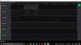
    Clearly, for the above code, master board (BL653) is transmitting the data just fine, along with controlling the cs, as in channel-2, channel-1 is MOSI & channel 0 is clock.


    Yet my slave board(nrf52833dk) is logging timeout:

    Kindly suggest Håkon Alseth, on how I can receive and print data on slave board.

    Thanks,

    Ubaid

Related